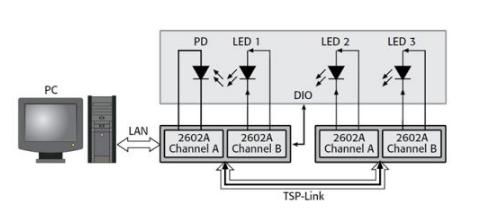
Visible light-emitting diodes (LEDs) combine high efficiency with long life. Currently, they are widely used. Manufacturers have developed new devices with higher luminous flux, longer lifetime, more color and higher lumens per watt through in-depth research. Accurate and cost-effective testing is critical to ensuring device reliability and quality. There are different types of test sequences at different stages of production, such as testing during the design development phase, wafer level testing during production, and final testing after packaging. Although LED testing generally includes electrical and electrical, this article focuses on electrical characterization and only introduces some optical measurement techniques at appropriate locations. Figure 1 shows the electrical IV curve of a typical diode. A complete test should contain a large number of voltage values ​​and corresponding current operating points, but in general a limited sample point is sufficient to test the quality factor of the device. Figure 1. DC IV curve and test point for a typical LED (not scalable) Many tests need to provide a known current and then measure the voltage, while others require a voltage and then measure the resulting current. Therefore, high-speed test instruments with integrated, synchronized source and measurement capabilities are ideal for this type of testing. Forward voltage test In the LED test sequence, the forward voltage (VF) test verifies the forward operating voltage on the visible LED. When a forward current is applied to the diode, it begins to conduct. At the beginning of the low current, the voltage drop across the diode rises rapidly, but as the drive current increases, the voltage slope begins to flatten. Diodes typically operate in a region where this voltage is relatively constant. It is also useful to test diodes under these operating conditions. The VF test needs to provide a known current and then measure the voltage drop across the diode. Typical test currents range from tens of milliamps to a few amps, and the resulting voltage is typically in the range of a few volts. Some manufacturers use the results of this test for device sorting because the forward voltage is related to the chromaticity of the LED (the color quality that is characterized by the primary or complementary color of the color and its purity). Optical test The forward bias current is also used for optical testing because the electron current is closely related to the intensity of the luminescence. The optical power can be measured by placing a photodiode near the device under test or capturing the emitted photons. The light is then converted to a current and the current is measured using an ammeter or a channel of the source measuring instrument. In many test applications, the voltage of the diode and the emitted light can be measured simultaneously using a fixed current source. In addition, spectrometers can be used to measure detailed parameters such as spectral output at the same magnitude of drive current. Reverse breakdown voltage test The reverse breakdown voltage (VR) can be measured by loading a reverse bias current to the LED. The magnitude of the test current should be set to a position where the measured voltage value no longer significantly increases when the current is slightly increased. When the voltage is higher than this voltage value, a large increase in the reverse bias current causes the reverse voltage change to be inconspicuous. This parameter indicator is usually a minimum. When testing VR, load a small reverse bias current for a certain period of time, and then measure the voltage drop across the LED. The size of the measurement is usually in the range of several tens of volts. Leakage current test Generally, leakage current (IL) is measured using a medium sized voltage (several volts to tens of volts). The leakage current test measures the small current leaking on the LED when the applied reverse voltage is lower than the breakdown voltage. Ensuring that the leakage does not exceed a certain threshold during the production process is a common practice for leak measurement and is more common for isolated measurements. There are two reasons for this. First, low current measurements require longer settling times, so they take longer to complete. Second, environmental and electrical noise have a large impact on low-value signals, so additional shielding is required. These additional shielding measures increase the complexity of the test fixture and can interfere with the operation of the robot. Intelligent instruments increase LED production test capacity In the past, in many LED production test systems, people often used PC to control all aspects of testing. In other words, in each component of the test sequence, each test must be configured separately for the source and test instrument, perform the required operations, and then return the data to the controlling PC. The control PC then performs a pass/fail judgment and performs a corresponding operation to sort the DUT. Each command sent and executed wastes valuable test time and reduces productivity. Obviously, in this type of PC-centric test structure, most of the test sequence time is consumed by communication between the PC and the test instrument. In contrast, many current smart instruments, such as the 2600A Series SourceMeter, make it possible to significantly increase the throughput of complex test sequences by reducing the amount of communication on the communication bus. In these instruments, the main part of the test sequence is embedded inside the instrument. The Test Script Processor (TSP?) is a versatile test sequence engine that controls test sequences and digital I/O ports with built-in pass/fail criteria, math, and calculation formulas. The TSP can save a user-defined test sequence in memory and execute it according to the command. This limits the setup and configuration time for each step in the test sequence and increases test throughput by minimizing communication with PCs and instruments. The programming process for this type of instrument is relatively simple: 1) create a script; 2) download the script to the instrument; 3) call the script to execute. For the 2600A Series instruments, users can write or download scripts using the Test Script Builder software provided with the instrument itself, or download them from the user application written in languages ​​such as Visual Basic or LabVIEW. Single LED device test system Figure 2 is a simplified block diagram of a test system for testing a single LED. For automated testing, a PC and a component robot are usually included - wafer probes require a probe station. Figure 2. Single LED test system block diagram based on digital source meter In this test structure, the main function of the PC is to save the measurement data in the database for data recording. The second role is to reconfigure the test sequence for different components. The 2600A Series is unique in that it can work independently of the PC controller. The embedded TSP on each instrument allows the user to write a complete test plan that can be executed on the instrument itself. In other words, the user can write a complete PASS/FAIL test sequence script that can be run through the instrument panel without instrument reprogramming. The production test system can use a component robot to transfer a single LED to the test fixture for electrical contact. The fixture shields ambient light and is equipped with a photodetector (PD) for optical measurements. In the configuration shown in Figure 2, a 2602A dual-channel source meter is used to implement the two connections. Among them, the source measurement unit A (SMUA) provides a test signal for the LED and measures its electrical response, while the SMUB is used to monitor the photodiode during the optical measurement process. The test sequence uses a digit line of the component robot at the beginning of programming as a "test enable (SOT)" signal. When the digital source meter detects this SOT signal, the LED feature analysis test begins. After all electrical and optical tests have been completed, the system sets a digital line labeled "Measurement Complete" for the component robot. In addition, the instrument's own intelligent function performs all pass/fail operations, sending a digital command to the component robot via the digital I/O port on the instrument, sorting the LEDs according to the pass/fail criterion. Then, you can set two operations to be performed simultaneously: transfer the data to the PC for statistical process control, and transfer a new DUT to the test fixture. Multi-device/array LED test system In the case of multi-device testing, such as testing involving aging, we are measuring multiple components simultaneously within a specified time. Driving a DUT typically requires continuous current, but multiple optical detectors can multiplex an ammeter through a switching system. The user can select the appropriate switching system and ammeter based on the dynamic range of the measured current. Multiple LED device tests can choose from many types of switches. For example, the Model 3706 Switch/Multimeter has six switch module slots, so it can support up to 576 multiplexed channels or 2,688 matrix intersections. Similar to the 2600A Series instruments, it also includes an onboard TSP and TSP-Link® inter-device communication/trigger bus that allows these instruments to be quickly and easily integrated into a single system. This integration supports tightly synchronized inter-instrument operation and allows them to operate under the control of a test script. Figure 3 shows the structure of a three-LED device test system with a photodiode (PD) channel. Figure 3. Block diagram of an LED array test system built with a scalable 2602A source meter channel Minimize LED test error Common sources of measurement error in LED production testing include lead resistance, leakage current, electrostatic interference, and optical interference, but self-heating is one of the most important sources of error. The two tests that are most sensitive to junction heating are the forward voltage test and the leakage current test. When the semiconductor junction heats up, the voltage will drop and, more importantly, the leakage current will increase during the constant voltage test. Therefore, it is very important to shorten the test time as much as possible without affecting measurement accuracy or stability. A smart instrument with an onboard test script engine simplifies the soak time of the device before the measurement is measured and the time it takes to acquire the input signal. All circuit capacitances are stabilized before the measurement begins during the holding time. Measuring the integration time depends on the number of power line cycles (NPLC). If the input power is 60 Hz, the 1NPLC measurement takes 1/60 second, or 16.667 ms. The integration time determines the time at which the A/D converter acquires the input signal, which compromises between measurement speed and accuracy. The typical holding time for VF testing ranges from less than a few hundred microseconds to 5 milliseconds, and the incubation time for IL testing ranges from 5 to 20 milliseconds. By utilizing these extremely short test times, it is possible to reduce errors due to junction heating. In addition, by performing a series of tests and testing only the test time, the characteristics of the junction fever can be analyzed. To further reduce test time and reduce junction self-heating effects, the 2600A Series instruments support pulse operation. In this mode, they are capable of producing a sophisticated source at the output for a specified period of time. The 1 microsecond pulse width resolution accurately controls the power-up time of the device. These instruments are also capable of outputting current values ​​that greatly exceed their DC capability in pulsed mode of operation. For example, the 2602A is capable of outputting 3A of DC current at 6V. In pulse mode, it can output 10A at 20V. RandM Switch Pro Rechargeable Electronic Cigarette 3200 Puffs 2 in 1 Shine Light Disposable Vapes,Salt Nicotine 6% Rechargeable Vape Pod Vape E Cigarette, 10ml E Liquid Disposable Vape Pen,Premium Quality 300PCS Master Case Rechargeable Disposable Vape Pod 3200 Puffs E Cigarette,Fruits Serise 10ml E Liquid Large Smoke Juce Liquid Vape Pen RandM Switch Pro,Disposable Vape with LED,Disposable Vape with LED Color Light,Electronic Cigarette Nanning Goodman Technology Co.,Ltd , https://www.goodmentech.com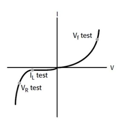

0 times
Window._bd_share_config = { "common": { "bdSnsKey": {}, "bdText": "", "bdMini": "2", "bdMiniList": false, "bdPic": "", "bdStyle": " 0", "bdSize": "24" }, "share": {}, "image": { "viewList": ["qzone", "tsina", "tqq", "renren", "weixin"], "viewText": "Share to:", "viewSize": "16" }, "selectShare": { "bdContainerClass": null, "bdSelectMiniList": ["qzone", "tsina", "tqq", "renren" , "weixin"] } }; with (document) 0[(getElementsByTagName('head')[0] || body).appendChild(createElement('script')).src = 'http://bdimg.share. Baidu.com/static/api/js/share.js?v=89860593.js?cdnversion=' + ~(-new Date() / 36e5)];
November 09, 2022