Production and circuit of FM wireless microphone
Production and circuit of FM wireless microphone
A FM wireless microphone and a FM receiver (or FM radio) with FM reception can achieve wireless transmission within a certain range, so that you can sing karaoke while walking at home. , Can also assist teachers to teach in large classrooms, etc. The wireless microphone circuit has a reasonable circuit design, beautiful and elegant appearance, a sound transmission distance of up to 20-30 meters, long service life, economical benefit, and low power consumption. Very suitable for the assembly and use of the majority of young radio enthusiasts.
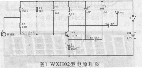
First, the working principle of the circuit Figure 1 is the circuit schematic of wxh02 wireless microphone. The circuit is mainly composed of an electret microphone and a high frequency triode 90l 8. Triode vt peripheral components l, c4, c5 and other peripheral components constitute a high-frequency oscillation circuit. The electret microphone BM converts the sound signal into an electrical signal, which is coupled to the base of vt through the electrolytic capacitor C1 to modulate the high-frequency constant-amplitude oscillating voltage. The modulated high-frequency signal passes through c6 and is emitted from the antenna. R3 and R4 are DC bias resistors of VT, r4 forms a DC negative feedback circuit, which makes the work of vt more stable. l and c5 determine the oscillation frequency, f = 1 / 2Ï€, adjusting the number of turns and spacing of l can change the oscillation frequency. R1 is the power supply resistance of the electret microphone.

Second, the choice of components
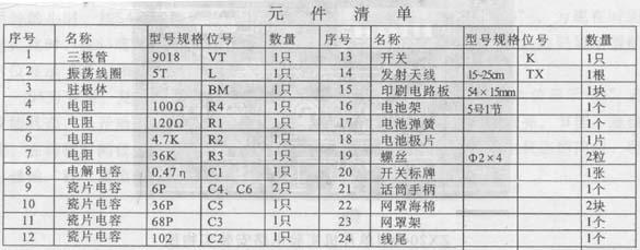
In addition to 9018, VT can use high frequency transistor with high cutoff frequency, such as 3dg80. c2, c3, c4 and c5 should use high-frequency ceramic dielectric capacitor with good stability, especially c5 must ensure the quality. Electret microphones use high-quality microphones. The oscillating coil l needs to be self-made, and the production method is to wind the flat shank drill with a diameter of φ5 mm by enameled wire with a diameter of φ0.5 mm and wind it 4 times. Other resistors can use the parameters shown in Figure 1.

3. The printed circuit diagram of the installation and manufacture of wxh02 wireless microphone is shown in Figure 2.
Before the installation and production, please use a multimeter to screen the quality of each component. If possible, measure the capacitance of each ceramic capacitor with a capacitance meter, so you will lose 10,000 yuan.
The order of installation is inductance coil, resistor, capacitor, high frequency transistor, microphone and toggle switch, battery clip. The purpose of classifying and installing components such as resistors and capacitors is to reduce errors and prevent the loss of components. Please refer to Figure 2 to determine the insertion holes of the above components. The two lead-out ends of the inductor coil are first scraped off the insulating paint on the surface, and then tinned. When inserting, they should be close to the circuit board and soldered firmly. If there is a virtual solder, the oscillation will be unstable and the work will be abnormal.
The purpose of the final installation of the triode is to minimize the damage to the tube caused by static electricity and heat during welding. Pay attention to the polarity when inserting and try to be as close as possible to the circuit board.
The electret microphone is led out by welding with two wires, pay attention to the polarity when welding to the circuit, and fix the welded microphone to the battery rack. The positive and negative springs of the battery are inserted into the corresponding parts of the battery clip, and the red and black wires are welded to the positive and negative springs, respectively, and lead to the circuit board.
The resistor and electrolytic capacitor are installed horizontally and close to the circuit board. The vertical installation of ceramic dielectric capacitors also needs to be close to the circuit board.
4. Set the power switch of the debugging wireless microphone to the "off" position, and set the multimeter to the "10mA" position. The two test leads are connected to the two ends of the power switch to measure the total current of the circuit. , The current is too large or too small (even 0) is not normal, should check the circuit board for wrong soldering, virtual soldering, short circuit, etc., and eliminate it in time.
Then turn on the radio (placed in the FM section) and the microphone switch k (placed on) and then hold the microphone and adjust the knob (or frequency selection key) while speaking to the microphone until your own voice is heard from the radio. If you still can't receive your voice in the entire frequency band (ie 88-108MHZ), carefully turn the oscillation coil l, you only need to pull apart or reduce the distance between each turn of the coil when turning, and you should be careful when adjusting. If the adjustment of the tightness of the coil still does not work, you should weld down one more turn or reduce one turn (due to the influence of the electronic component parameters), continue the above adjustment after re-welding.

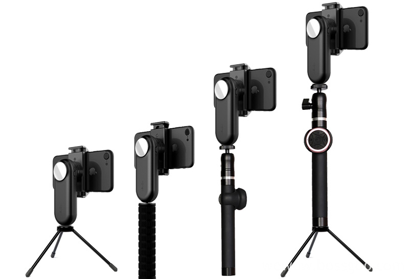
Single-Axis Stabilizer is a pivoted support that allows the phone or Gopro staying stabilized. With a gyro-stabilized gimbal system, it keeps stabilized or steerable horizon with automatic calibration to give you an unprecedented smooth shooting experience.

With the 1/4" Screw Adapter at the bottom, these handheld gimbal stabilizer can be matched with multiple filming accessories.

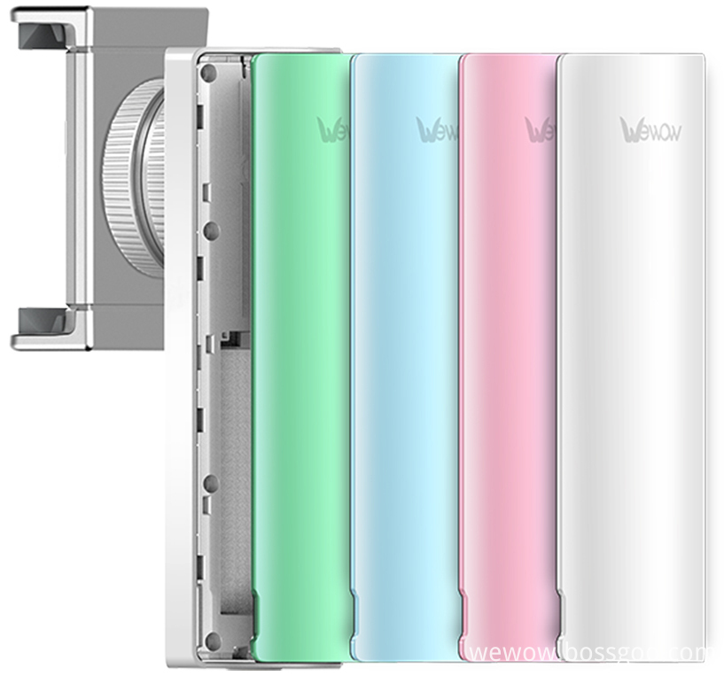
Smartphone Gimbal are designed as pocket size, portable and easy to take. You can carry it as easy as smartphone!

Wewow focusing on handheld stabilizer is a technology company which does R & D independently. With Wenpod series product released, the company achieved the industry's praise and quickly became the leader of the smart stabilizer industry.
Our service
1. Reply to you within 24 hours.
2. Already sample: within 1-2days.
3. Shipping date: within 24 hours once get the payment.
4. 12 months warranty.
5. After-sales service, solve within 3 working dates.
If you have any questions, please contact with us directly.
Wewow appreciates domestic and international business relationship!
Single-Axis Stabilizer,Professional Single-Axis Stabilizer,Single-Axis Stabilizer Kit,Stabilizer With Single Handheld
GUANGZHOU WEWOW ELECTRONIC CO., LTD. , https://www.stabilizers.pl