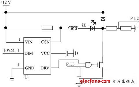
Abstract: Solar LED lighting systems, as green energy sources, have been widely used in recent years. This paper introduces you to a simple, reliable and easy-to-use solar landscape lighting control system. The system realizes the light intensity and color control of the lighting unit in the system through the ZigBee wireless sensor network architecture, and uses the polling mechanism to solve the real-time collection of the status of each lighting unit. And the broadcast frame synchronization cooperative lighting unit completes the scene conversion, and all system information is centrally processed by the upper computer control software through the GPRS network. 1 system structure The landscape lighting system is mainly composed of three parts: lighting unit, scene controller and monitoring host, as shown in Figure 1. The landscape lighting system staff realizes the detection, management and control of the working status of each lighting unit of the entire landscape system through the monitoring host. A monitoring host is set up in the system. The host computer is a computer connected to the Intenet and installed the landscape lighting system monitoring software. . The scene controller and the lighting unit it controls are the basic building blocks of the system. The monitoring host maintains information interaction with the system through the Internet and the GPRS wireless network. The number of scene controllers is determined according to the landscape lighting scale and the application environment, and each scene controller controls 1 to 127 lighting units to operate. Because landscape lighting has lower real-time requirements than industrial control systems and requires less information to be transmitted, the landscape system local communication uses ZigBee wireless sensor network (WSN), the lighting unit completes the WSN sensor network device function, and the scene controller The wireless sensor gateway function is implemented and acts as a co-ordinator of the respective sensor network, which is responsible for the networking and data transfer management of each sensor device. In addition to the completion of the sensor device function, the lighting unit in the system needs to complete the work of collecting the detection data of the lighting unit, sending data according to the system requirements, battery charging management, lighting control, and the like. Figure 1 Landscape lighting system composition 2 functional design 2.1 Lighting unit The main components of the lighting unit include a solar panel (group), a power management module, a battery (group), an LED light control module, and a wireless transceiver module. The solar panels (groups) convert the light energy into a current and charge the battery (group) via the power management module. After the landscape lighting system is turned on, the power management module converts the stored energy of the battery (group) into 12V DC required for LED lighting, and the power module detects the voltage of the battery in real time. When the battery voltage is lower than the threshold, the module automatically turns the LED power supply. Enter the mains and complete the conversion from 220V AC to 12V DC. The LED light control module needs to complete the switching, coloring and dimming of the LED light according to the scene setting. LED lamps are currently packaged in 1W or 3W lamp beads, which emit different colors of light through different phosphor LED beads. LED lamp beads are packaged in series, parallel, and hybrid. The LED lamp bead package can be selected according to the color requirements and brightness requirements of landscape lighting. In order to achieve better color reproduction in the landscape lighting system, the system uses red (R), green (G), and blue (B) three-color lamp beads to uniformly package the hybrid mode. The LED light control module controls the brightness of the RGB three color light beads, and forms a plurality of colors through the lens. Controlling the brightness of the LED lamp bead can be realized by changing the LED lamp bead current and adjusting the LED lamp bead lighting time. Relatively changing the current adjustment method, using the LED high-flashing feature to change the LED lighting time is simpler and easier to implement, is currently The main method used to adjust the brightness of the lamp bead. Figure 2 is a schematic diagram of the control principle of a lamp bead (red) in an LED lamp. The integrated circuit U1 is a constant current source chip (XLT604), and supplies power to the red, green and blue lamp beads, and the PWM pin control generates a constant current. Source current size. The P1.5 of the MCU sends out a PWM signal. The duty cycle is different, which causes the red bead to illuminate at different times, so that the red bead emits different brightness. The high and low levels of the MCU P1.2 pin are used to judge whether the red bead is damaged. . Figure 2 LED lamp bead control circuit. Crystal Pod Vape 2500,Vapingmuster Pro Disposable Vape,Vapingmuster Crystal Vape Pod Vape,Vapingmuster Pen Hookah Electronic Cigarette Shenzhen Niimoo Innovative Technology Co., Ltd , https://www.niimootech.com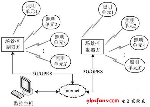
March 03, 2024