In order to meet the needs of human joint motion model research, a limb movement pattern acquisition system based on machine vision was designed. The system consisted of PCI-1411 video capture card and LabVIEW digital image processing platform. By processing the video frame of the acquired limb motion state, the mathematical model of limb joint motion is established, and the more accurate limb motion parameters are obtained. The research results show that the model established by the video acquisition technology has better advantages than the sensor acquisition technology, such as high precision, fast processing speed, small system error and easy data analysis and processing. This article refers to the address: http:// Shenzhen Yetnorson Technology Co., Ltd. , http://www.yetnorson.com
Keyword video capture; LabVIEW; digital image processing; limb motion model
The study of limb movement process is an important research object in the disciplines of kinematics, life sciences, automatic control, etc. The most typical application is robot research, and the results can be applied to the design of human prosthesis. The current prosthetic design technology makes the product expensive and complicated to control, and can not meet the needs of the majority of people with disabilities. To improve the living conditions of people with physical disabilities and promote the development of prosthetic design and production techniques, it is of great practical significance to study prostheses with simple structure, realistic gait and low cost. The establishment of limb movement model is a key research in prosthetic design. content.
The research of traditional limb motion process has been used as a model acquisition system by various mechanical simulation and digital conversion devices. This system has caused large distortion of the model due to systematic errors caused by a large number of data acquisition and processing tasks. With the development of information technology, video acquisition and digital image processing technology have been applied to various measurement and control fields due to their convenient acquisition, fast processing speed and high precision. Among the many video capture and processing solutions, National Instruments' video capture card PCI-1411 and LabVIEW processing platforms have powerful video capture and data processing capabilities. The video acquisition system designed by the development platform is used to establish the limb motion model. The target is the human lower limb movement process. The LED point light source is installed at the tip of the toe, the ankle joint, the knee joint and the thigh end joint, which can accurately collect the limbs. The trajectory of the movement, thus establishing a complete model of the limb movement process. The basic principle is to collect the point light source motion sequence fixed at the joint of the limb in real time through the camera, and use the digital image processing technology and video connection technology to draw the stick map of the motion track of the limb. The limb motion model is constructed by coordinate the coordinates of the light spot. Applying the knowledge of mathematical geometry measurement to the motion model, obtaining the model parameters of the limb movement, and establishing a mathematical model of the limb movement.
1 Construction of limb movement model acquisition system The limb motion model acquisition system constructed by video capture method is composed of video acquisition device and video processing software. The video acquisition device includes a point light source, a video camera, a video capture card, and a PC. The point light source uses a 1 W red LED to fix it at the joints of the limbs. The camera uses a Timber 2038 interline conversion CCD camera with 794 594 pixels and 540 lines of horizontal resolution. The maximum aperture is 0 when the maximum aperture is F1.2. 000 1 Lux, the maximum image acquisition rate is 30 frames / s, the camera lens is manual aperture, the focal length is 3.5 ~ 8 mm, and the video capture card uses NI PCI-1411. The video acquisition software uses NI's IMAQ Vision module, which has many sub-function libraries such as image acquisition, system calibration, image processing, geometric measurement, image segmentation, etc., which can complete image denoising, enhancement, restoration, segmentation and extraction features. , gray and binary image processing and shape matching, speckle analysis, statistics, filtering, geometric transformation, calculation and measurement tasks; video processing software is written in the G language virtual instrument development platform LabVIEW, mainly using the data stream driving method, After compiling, the running speed is close to C language, and it can drive many data acquisition cards from many manufacturers. It has powerful data acquisition capability and signal processing function, which can express programming algorithms intuitively and efficiently.
2 Spot detection principle The installation position and detection of the point source is the basis for establishing a complete and accurate motion model. The core problem of model building accuracy is to complete spot detection and make it highly robust.
Since the red LED is detected, the R component of the spot is dominant. Therefore, the background subtraction method is adopted in the paper, and only the R component is read in the process of reading the background frame and the current frame, thereby improving the operation efficiency. The differential image of the background image bk and the current frame image fk is calculated by the equation (1), thereby detecting the moving target region Dk(x, y)=|fk(x, y)-bk-1(x, in each frame of the image. y)| (1)
Where fk(x, y) and bk-1(x, y) are the current frame and background frame R component images, respectively, and Dk(x, y) is the R component difference image obtained by the background difference.
The moving target area in each frame image is detected, which overcomes the influence of the ambient light field instability factor on the detection result, improves the detection precision of the moving object edge, and lays a foundation for the subsequent effective restoration of the connected limb motion model.
The spot detection method can more accurately identify the position of the light-emitting point by filtering and denoising the characteristic parameters of the light-emitting point, and then complete the measurement of the limb motion process through accurate coordinate system positioning, which is a parameter of the limb motion model. Acquisition and measurement of limb feature parameters provide a complete basis for implementation.
3 Connection recovery of the limb motion model and mathematical model establishment The segmentation map obtained by the spot detection can completely identify and extract the light-emitting points installed at each node of the limb, as shown in Fig. 2(a). Apply LabVIEW to mark the coordinates of each spot. Using the spot connection technology, connect the four light-emitting points on each frame image one by one to obtain a static model representing the soles of the feet, calves and thighs, as shown in Figure 2 (Figure 2 ( b) shown. In each static model, the actual length represented by each pixel value is calculated by analyzing and comparing the pixel values, and then the length of the foot, the length of the leg and the length of the thigh are converted. This method of video measurement is more than the actual measurement. The method is more precise and provides reliable data for subsequent model analysis. At the same time, by measuring the angle of the connected model relative to the vertical position, the relationship between the angle of the sole, the calf and the thigh relative to the vertical direction can be measured, and the relative vertical angle relationship between the models of each adjacent frame and the time is recorded. The coordinates are shown in Fig. 2(c), and a function fitting map of each angle and time can be obtained, as shown in Fig. 2(d) and Fig. 2(f). According to the relationship between the change of the angle of the legs and the time, the function relationship between the angles of the legs and the legs can be calculated. As shown in Fig. 3(e), three representative models can be obtained, such as equations (2) to (5). ) shown. 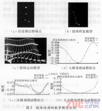
The correlation function obtained by the fitted curve is as follows: 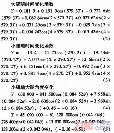
4 Model simulation and results verification Simulation and results testing is a key step to achieve the model, and an important part of the realization of prosthetic design. The purpose of the simulation is to simulate a thigh with an ever-changing angle. By detecting the angle of the thigh, the established function model is used to control the calf swing. In this control process, since the position of the knee joint moves continuously while walking, it will lead to the transformation of the coordinate system. In order to better realize and accurately represent the transformed coordinate system, the length of the size leg is introduced into the coordinate transformation. In the middle, according to the length of the leg, the angle at which the calf will be adjusted and the coordinates of the ankle joint are calculated. The equations of the coordinate transformation are as follows 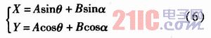
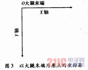
Where θ is the angle between the thigh and the vertical direction; α is the angle between the calf and the vertical direction calculated by the model control; A is the length of the thigh; B is the length of the calf; (X, Y) is the end of the thigh The position in the label of the origin of the coordinate.
The model established by the ankle joint coordinate transformation can observe the movement state of the thigh to control the posture of the lower leg in the simulation. In order to verify the correctness of the model, a single-chip computer is used to control the motion of the stepping motor. A program simulating the thigh swing process is designed on the robot joint to simulate the thigh swing. The tilt sensor fixed on the robot thigh is used to detect the angular change of the simulated thigh. The STC89C52 MCU controls the steering gear mounted on the knee joint of the robot according to the established relationship between the size and leg motion function, and drives the calf to swing. The observation results show that the motion posture of the calf is simulated within a certain precision range, which is consistent with the movement pattern of the human leg. It is feasible to demonstrate the motion model established by the human leg model acquisition system. The limb model function can be applied to the design of the prosthesis.
5 Conclusion Based on the video capture system's limb modeling, a method of establishing a limb motion model with high precision and small error is provided, which provides a direction for the study of limb movement and lays a foundation for the realization of low-cost prosthesis design.
September 15, 2019