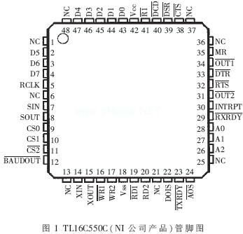
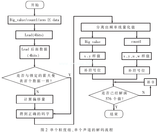
The TMS320VC5509 (hereafter referred to as C5509) is a new generation product of TI's C5000 DSP series. The minimum operating voltage of the chip is 0.9V, and the minimum power consumption of the core is only 0.05MW/MIPS, and the performance is up to 800 MIPS. The C5509 provides an effective solution for embedded DSP applications and applications such as high performance instrumentation, intelligent robotics, handheld devices, digital audio players and digital cameras. MP3 refers to the third layer of encoding/decoding of MPEG (Moving Picture Experts Group) international standard audio. MP3 encoding is realized by converting audio signals from time domain signals to frequency domain signals and removing some redundant information according to human psychoacoustic features. Detailed coding/decoding standards are given in ISO/IEC 11172-3 Part 3. The decoding involves complex arithmetic modules such as Huffman decoding, modified cosine inverse transform (IMDCT), and subband synthesis. This paper uses C5509 to realize the decoding operation of MP3. This article refers to the address: http:// 1 C5509 DSP processor features and working principle 1.1 Overview of the performance of the C5509 DSP C5509 has 32×16bit instruction buffer queue for efficient block loop operation; two 17×17bit MAC units can perform two MAC operations in a single cycle; one 40bit ALU and one 40bit bucket shift The bit shifter, four 40-bit accumulators can perform more efficient arithmetic operations than the C54 series DSP, and can achieve 800 MIPS performance with a 400 MHz crystal oscillator. Taking an MP3 data stream with a sampling rate of 44.1 kHz as an example, the MP3 data at a data rate of 128 kbit/s is decoded. Huffman decoding, IMDCT, sub-band synthesis and other computing modules need to consume 1.3 MIPS of CPU resources. For an average of 44.6 frames per second, the total computational load is 44.6×1.3=57.98 MIPS. C5509 can fully satisfy this. Speed ​​requirements. The C5509 also has 128K x 16bit on-chip RAM, including 64KB of DARAM, 192KB of SARAM, and 64KB of on-chip ROM. Like many TMS320 series DSP processors, the C5509 uses Harvard architecture and has 12 independent buses, including 3 sets of data read bus, 2 sets of data write bus, 5 sets of data address bus, 1 set of program read bus and 1 set of programs. Address bus, these buses provide instructions and opcodes for each computing unit in parallel, providing a powerful guarantee for high-speed data operations. 1.2 Introduction to peripherals of C5509 DSP The C5509 provides a dedicated External Memory Interface (EMIF) for controlling the transfer of all data between the DSP and external memory. Memory that can be seamlessly linked to EMIF is: asynchronous memory (ROM, FLASH, SRAM), synchronous burst SRAM, synchronous DRAM (SDRAM), and supports optional 32, 16, and 8-bit data access. When programming EMIF, it is necessary to consider how to allocate the on-chip enable space (CE) based on the actual external memory. The EMIF interface allows the host processor to place data and programs off-chip, saving on-chip hardware resources. Secondly, the C5509 has three independent multi-channel buffer serial ports (McBSP), which enables the C5509 to directly interconnect with other C55xx series DSPs, multimedia digital codecs and other devices. These McBSPs can provide full-speed duplex communication and support 128. Channels can be selected for transmission, reception, or transmission using separate clocks with word widths of 8, 12, 16, 20, and 24 bits. In order to ensure data communication with common asynchronous communication modules, C5509 provides a UART interconnected with a dedicated asynchronous communication interface IC such as TL16C550C. External data enters and exits the DSP UART via TL16C550C, and finally passes to the on-chip CPU for processing. Figure 1 shows the pinout diagram of a typical dedicated asynchronous communication interface IC (TL16C550C) used with the C5509. Each time the C5509 UART receives data, it will generate a corresponding interrupt request, informing the CPU to collect data in time, and put the serial data on the Rx line into the receiving register. After the buffer length is satisfied, the parallel data of the register is handed over to the CPU. Do follow-up processing. 2 decoding algorithm description 2.1 Format of MP3 files The MP3 file is based on frames, and the composition of each frame is shown in Table 1. Since the MP3 file data format adopts the bitpool technology, the main data may be before the frame header, and the specific position may be obtained by the main_data_begin variable included in the frame side information. When decoding, first read a certain length (2kbit of the system) data into the internal RAM of the C5509, and then look for the sync word sync_word (FFF) of the frame. If a sync word is found, the 32 bit headed by it is the frame header. It is known from the check bits in the frame header whether there is check data. If not, the subsequent 256-bit data is the frame side information. The main data generally contains data of two granularity groups (gr), each of which contains data information of two parts of the left and right channels (ch), and each channel data can be independently decoded, so that each granularity of each granularity is decoded. The program is written as a single *.c file to accommodate decoding in mono or other MP3 formats. MP3 coding according to human psychoacoustics, each particle size component is three parts of data: the first part corresponds to the low frequency sampling Big_values ​​(large value area), the larger absolute value of the quantized value is used to store the low frequency value; the second part is the Count1 area, The intermediate frequency value is stored by the quantized value with a smaller absolute value. The possible values ​​of all the quantized values ​​are 1, 0, -1; the third part is the Zero high frequency region with zero code, and the zero data does not need to appear in the MP3 file, only It is necessary to ask at the time of decoding whether the count of each granularity group has reached 576. If the count is 576, it indicates that the granularity group has solved the quantized values ​​of 576 frequency lines. The above frame side information stores all important information for subsequent decoding. For ease of reference, define it as a structure. The definitions and comments for some of the elements are as follows: Struct Granule { The value of table_select[3] is the subscript h of the Huffman table, which can lock a specific Huffman table when solving the main data. 2.2 Huffman decoding principle of MP3 data As described in the previous section, the data for each granularity group divides the frequency line from 0 to the Nyquist frequency into three regions Big_values, Count1, and Zero according to acoustic characteristics. In the decoding, the Huffman code table format corresponding to the Big_values ​​area is as shown in Table 2, and the Count1 area code table format is as shown in Table 3. The file huffman.h storing the Huffman code table contains 32 code tables for the Big_values ​​area query and 2 code tables for the Count1 area query. In order to quickly find the short-length code value, the auxiliary table h_cue[34][16] is also added. When starting to solve the main data, the fixed-length (for example, 32-bit) data dataword() is pushed onto the stack, and the first four bits of the buffer are first removed as the header data of the auxiliary table, and then according to the lead value and the frame side information. In the Huffman lookup table subscript h, the specific data of the auxiliary table h_cue[h][lead] is obtained. This data only points to the first address h_tab of a table in the Big_values ​​area or the Count1 area, which is used in the table. Which data still needs the program to provide an offset to continue to judge. At this point, the data of the lead four bits can be removed from the buffer area and compared with the locked Huffman table. If the data behind this is consistent with the code word of the locked Huffman header, the decoded data can be obtained immediately. If the two codewords are inconsistent, the offset of h_cue[h][lead] and h_cue[h][lead+1] is also obtained, so that the correct decoded data is finally obtained. (The format is shown in Table 2 and Table 3). In addition, since the quantized value whose absolute value is less than or equal to 15 is directly encoded in the MP3 encoding, ESC (additional value) encoding is used for the quantized value whose absolute value is greater than 15, so that it is necessary to determine whether or not to add an additional value after obtaining the overwritten data. And the sign bit. The detailed decoding process is shown in Figure 2. 300 - 1000 Puffs (included) Shenzhen Zpal Technology Co.,Ltd , https://www.zpalvapes.com

Unsigned part2_3_length; / / used to calculate Count1
/ / location;
Unsigned big_values; / / used to calculate Big_values
/ / location;
Unsigned table_select[3]; //Use to determine which // Huffman table to look up;
......
}; 


The main computational complexity of MP3 decoding is concentrated in the four arithmetic modules of Huffman decoding, inverse quantization, IMDCT, and subband synthesis, and Huffman decoding accounts for 1/5 of the total of the total computation. Using the profile tool of CCS to estimate the computational complexity of the 44.1 kHz sampling rate and the MP3 data of the bit rate of 128 kbps, the computational complexity consumed by the decoding module of the system is 1.3 MIPS. It can be seen that for real-time decoding of more than 50 frames per second, the DSP must bear the computational complexity of 65 MIPS, and the decoding module implemented by the DSP is fully capable.
December 15, 2023