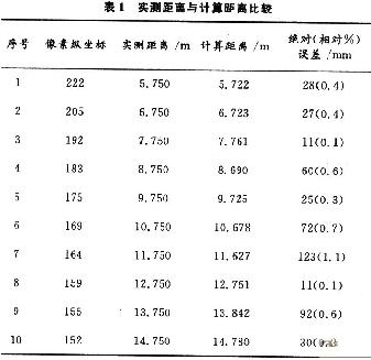
0 Preface The use of image sensors to sense the road traffic environment and the position of obstacles ahead, to achieve safe distance measurement, timely warning of cars in danger of collision is conducive to reducing traffic accidents and improving road traffic safety. Since the theoretically calculated safe distance must first be based on the guarantee of safety, there is often a large discrepancy with the safe distance recognized by the driver during driving, resulting in the driver ’s distrust of the early warning system, which is not conducive to the promotion of the system use. At the same time, as the processing platform of the safety-assisted driving system, the size, cost and redundancy of functions of the PC are the bottlenecks that are difficult to overcome in the vehicle-mounted system. In this paper, based on the image measurement of the distance between the vehicle and the vehicle in front, a longitudinal collision warning model of the vehicle is established to solve the contradiction between the theoretically calculated safety distance and the driver's habitual distance; the real-time processing of the embedded system is considered With the characteristics of small size and compactness, the embedded method is used to complete the design of the vehicle longitudinal collision warning system. 1 Measurement of the distance ahead The image sensor is fixed on the top of the front end of the vehicle, and the height of the camera from the ground is h. Establish the spatial coordinate system as follows: World coordinate system XYZ and camera coordinate system xyz. The dynamic world coordinate system moves with the vehicle, with the vertical projection point of the camera lens center on the ground as the origin, the vertical line of the ground upward is the Z axis positive direction, the longitudinal axis of the body is the X axis, and the positive direction is the reverse direction of the car. ; The camera coordinate system uses the optical axis as the z-axis, the lens center as the coordinate origin, and the camera coordinate xy plane is parallel to the image plane; the u-axis, v-axis of the image plane coordinate system that characterizes the position of each point in the image are parallel to the x-axis and y-axis , The origin is located in the center of the image, which is the intersection of the optical axis of the camera and the image. All coordinate systems satisfy the right-hand rule. The measurement of the vehicle or obstacle in front by the image sensor includes ranging using a single frame image and ranging using a multi-frame image. In the study, the installation position parameters of the camera are considered. The angle of the camera's z coordinate axis relative to the X axis is called the sweep angle β, and the angle of the camera's optical axis (z axis) relative to the vertical direction (Z axis) is called the tilt angle α. As shown in Figure 1. In the figure, the external parameters α, β, h of the camera and the internal focal length f of the camera are obtained by strict camera calibration. The image features of the vehicle and the Kalmam filtering principle are used to identify the vehicle, and the computer image coordinates of point P at the bottom of the vehicle are known. The point (u0, v0) is the origin of the image plane coordinates (O, 0); the point (u, v) can be calculated from the point P computer image coordinates (m, n) according to the internal parameter model formula In order to verify the calculation accuracy of formula (1), after the camera calibration is completed, the crosswalk line of the road is photographed, and the horizontal distance between each crosswalk line and the center of the camera lens is measured and compared with the distance calculated according to the distance measurement model. The results are shown in Table 1. As shown. In the table, the error between the measured distance and the calculated distance includes measurement error and model error. It can be seen from the table that the error is within the allowable range and can meet the next processing requirements.
What is a data cable
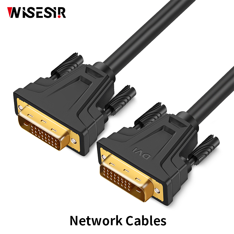
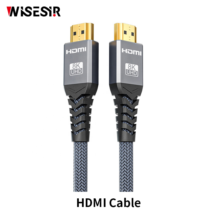
A data cable is used in establishing connections between multiple computers over a network. To use this, an ethernet cable is utilized. The ethernet cable uses the network interface to connected PCs.We have several kinds of data cables: USB Cable ,Micro cable,Cable for apple, HDMI Cable ,Displayport Cable,Thunderbolt Product and so on.
Usb Data Transfer Cable,Best Data Cable for Fast Charging,Best Hdmi Cable,Docking Station for Laptop,fast charging data cable for huawei mobile phone Pogo Technology International Ltd , https://www.pogomedical.com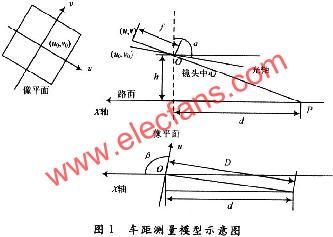
![]() obtain. Among them, kx, ky is the magnification factor of the digital image in the x-axis and y-axis directions; Om, On is the computer image coordinates of the origin of the image plane. According to the perspective projection and the triangular geometric relationship, the distance between the two vehicles is calculated by equation (1):
obtain. Among them, kx, ky is the magnification factor of the digital image in the x-axis and y-axis directions; Om, On is the computer image coordinates of the origin of the image plane. According to the perspective projection and the triangular geometric relationship, the distance between the two vehicles is calculated by equation (1): 
May 11, 2024