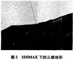
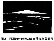
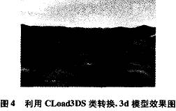
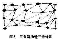
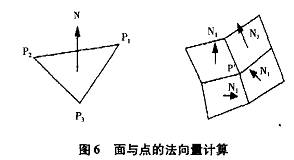
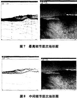
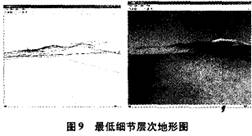
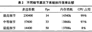
Research on Terrain Modeling and Realization Technology in 3D Visualization 1 Introduction After the 1960s, the concept of terrain visualization was gradually formed with the emergence of geographic information systems. Subsequently, the terrain 3D visualization technology focused on terrain and landforms was used in geographic information systems (GIs), virtual reality (VR) battlefield environment simulation, entertainment games, terrain flight ({1yin hr0ugh) land management and utilization, and hydrometeorological data visualization It has been widely used in many fields, and has attracted more and more attention. Crucible visualization ... is a 3D solid construction technology that focuses on the display, simplification, and simulation of digital terrain model (Digital Terrain M0de1) or digital elevation domain (Di gital ElevaTI0n Fie1d), and is an important component in the construction of 3D scenes Part and research focus. Based on the realization technology of i-dimensional terrain based on OpenGL, this paper analyzes different key technologies such as three-dimensional terrain model method and three-dimensional sting, focusing on two types of one-dimensional terrain modeling based on 3DsMAx and 0penGL. The technology is implemented, and its performance is compared based on the number of polygons, frames per second, memory usage, and cPu efficiency. Finally, according to the results of their performance comparison and their respective characteristics, the applicable occasions of different methods are given, so as to provide a basis and guidance for terrain modeling and implementation technology selection in practical engineering applications. 2 Three-dimensional terrain modeling and implementation method 2.1 Terrain modeling Currently, there are two conventional modeling methods for constructing three-dimensional solids using 0penGL technology: 1) Complete the construction of the body in the three-dimensional body construction software (such as 3DsMAx, etc.), convert the model established by 3DSMAx into the vertex array in 0penGL through the corresponding method, and finally display it under 0penGL; 2) 0penGL programming is used to realize 3D terrain modeling. At present, the commonly used method is to first build a terrain model according to the feature point elevation and terrain feature parameters (such as average elevation, elevation standard deviation, etc.), and then use interpolation to generate the details of the terrain. Texture processing forms a complete three-dimensional terrain. 2.2 The basic method of 3D terrain realization In the implementation process, first obtain DEM H data (image data) through corresponding data processing, convert the original data into the vertex data needed for the three-dimensional model construction; and use the transformed data for model construction, through projection transformation, viewpoint transformation After a series of steps, the initial three-dimensional terrain is formed; finally, the post-processing and processing of light blanking and texture mapping technology are used to form the realistic three-dimensional terrain. The basic realization process of three-dimensional terrain based on OpenGL technology is shown in Figure 1, and this article will focus on the construction method of the three-dimensional digital terrain model in the basic process. The following will introduce the modeling technology and implementation method of building 3D terrain using 0penGL technology. 3 Terrain modeling and implementation based on 3DSMAX First, use the processed DEM data to build a digital terrain under 3DsMAx software (see the relevant technical literature for specific methods and steps of 3DsMAx modeling). The digital terrain built through 3DSMAx is shown in Figure 2. When the 3DsMAx model is built, you need to convert this model to a vertex array in 0pen-GL. There are three ways to achieve the above conversion: 1) Read the 3DsMAx model directly, and put all the information into the corresponding array; 2) Using tool software such as Deep ExploraTIon, etc., you can convert the 3DSMAX model to a C language file, and store the model information in an array in the c language file; 3) Use the packaged 3DsMAx file reading class for model conversion. If the widely used cIJoad3Ds class J is written and packaged by professional personnel, it can be completed by including its header files and execution files and calling the corresponding functions. Conversion of 3d model. Each of these three methods has advantages and disadvantages. The advantage of the first method is that you can choose to store information that is useful to you, filter out the information you don't care about, and improve the efficiency of the program. The disadvantage is that users need to be right. The 3d file structure has a deeper understanding and requires a lot of programming, which is time-consuming and laborious; the advantage of the second method is that it does not require a professional. 3D file structure knowledge, directly converted by software, saves time and effort, the disadvantage is that most software can only convert the vertex data in 3DsMAx into an array to save, but will lose texture information, as shown in Figure 3; the third method is better Solves the shortcomings of the first two methods, it can easily convert the 3DsMAx model without losing texture information, as shown in Figure 4. But the disadvantage is that it completely saves all the information, so that when OpenGL is rendered, it will increase the amount of computing and reduce the efficiency of the program. The use of the first method and the third method are technically consistent, both through the right. The information of the 3d file is categorized for reading. The difference is that the first method requires self-programming, and the third method uses existing programs. Compared with the third method, the second method saves all vertex data, but it can selectively draw useful vertices in OpenGL. In order to compare the two methods to the same one. The efficiency of the conversion of the 3d 3D terrain model is specifically measured by the number of polygons, frames per second (Fps), memory usage, cPu usage, etc. The comparison results are shown in Table 1 (the computer configuration used for testing As follows: PenTIum (R) M 1. 4G processor, memory is 512M, operating system is wind0ws xP). In summary, for. The second method of 3D 3D terrain conversion is not suitable for the conversion of models with high texture requirements. Whether to use the first method or the third method should be selected according to different situations: 1) When the system has high real-time requirements and large terrain, and the development time is ample, choose the first method; 2) When the system pays attention to development, and can tolerate a certain efficiency loss, choose the third method. [ 4 Terrain modeling and implementation based on openGL technology â‘ Basic terrain modeling All smooth surfaces in computer graphics are ultimately obtained by infinite approximation of polygons (mainly triangles), so the essence of building a three-dimensional terrain model is to construct a spatial triangle network to approximate the surface. Use the prepared data points to generate a triangular network according to the Delaunay triangular network construction rules, as shown in Figure 5. After generating the triangulation network, it is also necessary to pay attention to the labeling of the normal vectors of the triangular surfaces that make up the triangulation network. Because the brightness of the generated terrain depends on the light source and the shading method, it is also affected by the normal vector of the triangle points and the surface. The normal vector of a general point is the average of the normal vectors of its surrounding surfaces. The normal vector at point P in FIG. 6 can be expressed as the average of the sum of the normal vectors N1, N2, N3, and N4 of the four surfaces adjacent thereto. â‘¡ LOD (Level 0f Defajls) technical terrain modeling L0D technology refers to the technology of realizing the real-time dynamic display of three-dimensional complex models, expressing three-dimensional objects with a variety of different precisions, and selecting models with different precisions for imaging according to the transformation of the position of the observation point. In general, the amount of terrain data is very large. Using a general method to build a large terrain requires a lot of memory and will also seriously affect the rendering speed. However, it is not that the system has to spend a lot of memory and CPu every time to render large amounts of terrain, because when the observation point is far away from the ground, the terrain image occupies few pixel points on the screen. In this case, it is not necessary to use a large number of polygon patches to accurately represent the terrain. Therefore, the system only needs to render a large number of polygons to approximate the real terrain when the observation point is very close to the ground and needs to describe the landform finely; when the observation point is far from the ground, the data volume can be simplified to improve rendering efficiency And the purpose of reducing memory consumption is to use IJ0D technology. The effects of using LOD technology for terrain modeling are shown in Figures 7, 8, and 9. Figures 7, 8, and 9 are the terrain modeling of the same set of terrain data at different levels of detail. The left picture is a grid picture, and the right picture is a solid picture. It can be seen from the left picture that the number of polygons rendered is significantly reduced, while the solid effect on the right picture will not change significantly when the viewpoint is far away from the ground. In order to specifically illustrate the efficiency improvement brought by LOD technology, Table 2 compares the number of polygons rendered at different levels of detail, frames per second (Fps), memory usage, and CPU usage (the test conditions are the same as above). From the performance comparison in Table 2, it can be concluded that the use of lower levels of detail has excellent performance in terms of improved rendering efficiency and reduced system consumption. This shows that using LOD technology to achieve large-scale three-dimensional terrain has practical engineering value. Therefore, using different levels of detail for 3D terrain at different observation heights can improve program efficiency without losing visual effects. 5 Performance comparison The above discusses two types of 3D terrain modeling and implementation technologies, and the pros and cons of these two different implementation methods still need to be compared and studied. In view of this, this article compares the Fps, memory consumption, and cPu efficiency indicators of rendering the same number of polygons by these two methods. The packaged cLoad3D class is used to convert 3DsMAx files. The computer configuration used for testing is the same as the test configuration above. The test results of performance comparison are shown in Table 3. It can be drawn from Table 3 that rendering the same number of polygons, OpenGL programming modeling uses less memory consumption and has higher Fps than 3DsMAx modeling. So if the program is biased towards the pursuit of program execution efficiency, it is better to use OpenGL programming and modeling. However, the advantages of 3DsMAx modeling are obvious. The 3D model built using the 0penGL program is rough in appearance, and has poor modeling intuitiveness and low efficiency when modifying the model. At the same time, the modeling process is cumbersome and the amount of programming is large. 3DsMAx is a professional 3D model. Model software, which can be used to easily build object models, and models can be built intuitively without programming. The model has a more refined appearance and can retain many details. When the program requires complex and detailed appearance of the three-dimensional terrain, it should consider using 3DsMAx modeling to achieve. 6 Conclusion From the perspective of the realization process of 3D terrain, this paper focuses on the realization method of 3D terrain modeling. It focuses on two types of 3D terrain modeling and implementation technologies supported by 0penGL, and compares its performance, advantages and disadvantages. Through the comparison and analysis of the performance, advantages and disadvantages of the two methods, the applicable occasions of different methods are obtained, so as to provide a basis and guidance for the selection of terrain modeling and implementation technology in practical engineering applications: 1) The system is more inclined to performance in terms of performance and effect, and requires less memory and cPu, then OpenGL programming is applicable; 2) The system is more inclined to the effect in terms of performance and effect, and has higher requirements for details. The texture mapping is complex and changeable, so it is suitable for 3DSMAx modeling. Disposable Pod,OEM Dispossble Vape,OEM Dispossble Electronics-cigarette Vape,OEM Vape Pod,OEM Vape Disposable Atomizer Pod TSVAPE Wholesale/OEM/ODM , https://www.tsecigarette.com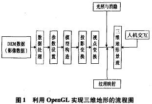


August 11, 2024