The basic schematic diagram of the basic flyback transformer switching power supply.
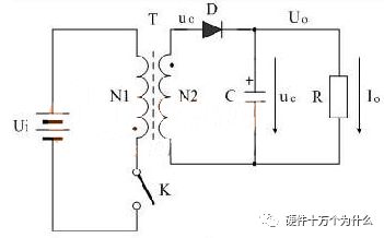
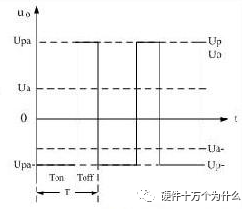
In this circuit system, Ui is the input voltage of the switching power supply, T is the switching transformer, K is the control switch, C is the energy storage filter capacitor, and R is the load resistance. The following figure shows the voltage output waveform of the flyback transformer switching power supply.
The switching power supply transformer and the switch tube together form a self-excited (or alternate) type of intermittent oscillator, which modulates the input dc voltage into a high frequency pulse voltage. In a flyback circuit, when the switch is turned on, the transformer converts electrical energy into a magnetic field that can be stored and released when the switch is turned off. In the forward-type circuit, when the switch is turned on, the input voltage is directly supplied to the load and the energy is stored in the energy storage inductor. When the switch is turned off, the energy storage inductors continue to flow to the load.
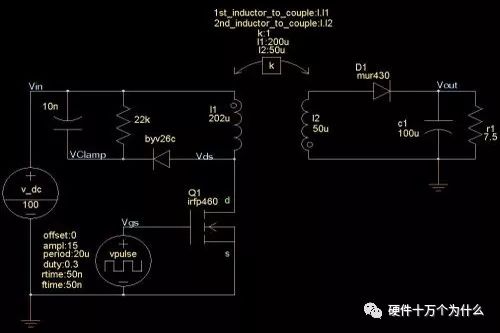
The primary inductance of the transformer is 202uH, while only 200uH is involved in the coupling, then 2uH is the leakage inductance. The secondary is 50uH and there is no leakage inductance. The inductance ratio of the transformer is 200:50, which means that the transformer turns ratio NP/NS=2:1 to set the transient sweep, the time is 10ms, the step length is 10ns, and the waveform at steady state:
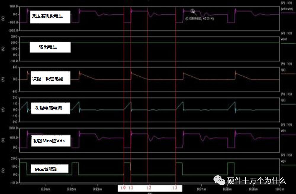
At t0, the MOS turns on and the primary current rises linearly.
At t1, the MOS is turned off and the primary induced electromotive force is coupled to the secondary to the output capacitor to transfer energy. Leakage inductance produces voltage spikes on the MOS. The output voltage is coupled through the winding and reflected to the primary according to the turn ratio. These are the same as in the CCM mode. This state is maintained until the end of t2.
At t2, the secondary diode current, ie the secondary inductor current, drops to zero. This means that the energy in the core has been completely released. Then, because the current in the two tubes drops to zero, the diode is automatically turned off, and the secondary is equivalent to the open circuit state, and the output voltage is no longer reflected back to the primary. Since the Vds voltage of the MOS is higher than the input voltage at this time, the MOS junction capacitance and the primary inductance resonate under the voltage difference. The resonant current discharges the junction capacitance of the MOS. The Vds voltage begins to drop and then begins to rise after one quarter of a resonant period. Due to the existence of the RCD clamp circuit, this oscillation is a damped oscillation with smaller and smaller amplitude.
From t2 to t3, the transformer does not deliver energy to the output capacitor. The output is completely maintained by the output storage capacitor.
At time t3, the MOS is turned on again because the magnetic core energy has been completely released before and the inductor current is zero. So the primary current rises from zero.
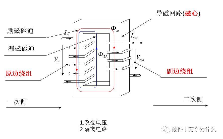
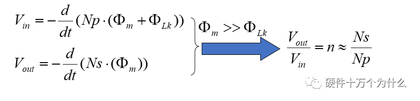
Voltage relationship of the winding - basic characteristics of the transformer
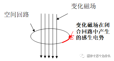
Faraday's law:
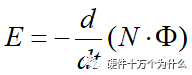
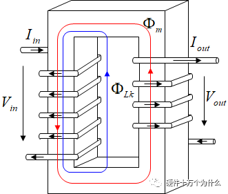
According to Faraday's law, the relationship between the input and output voltage is obtained: Turns ratio
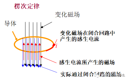
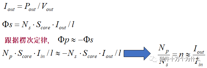
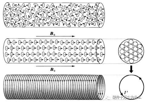
Lenz's Law -- Transformer Current Relationship
The direction of the induced current in the closed loop always causes the magnetic field it excites to “hinder†the change in magnetic flux that induces the current.
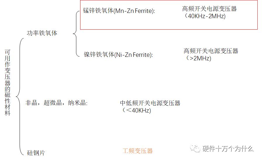
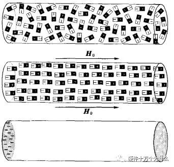
Can be used as magnetic core material of transformer core
Select the key points of magnetic materials:
A: saturation magnetic density of magnetic core
B: Core loss (difference between energy storage and energy release)
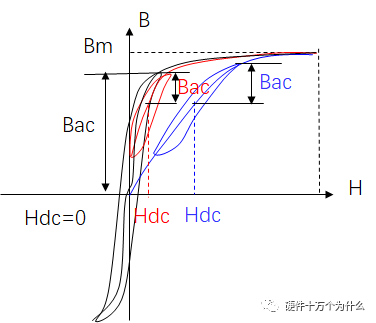
About saturation magnetic density:
Magnetic saturation is a physical property of a magnetic material. It refers to the limitation of the physical structure of a magnetically permeable material. The magnetic flux passing through it cannot be increased indefinitely to maintain a certain number of states.
Magnetic saturation is a physical property of a magnetic material. After magnetic saturation is generated, it is harmful in some cases, but sometimes it is beneficial. For example, a magnetic saturation regulator utilizes the magnetic saturation characteristics of a core to achieve a stable voltage. The power transformer, if the voltage applied exceeds the rated voltage, the current increases rapidly and the transformer will soon heat up and burn.
Assuming that there is an electromagnet, when a unit current is applied, the magnetic field induced intensity is 1. When the current increases to 2, the magnetic induction intensity increases to 2.3. When the current is 5, the magnetic induction intensity is 7, but the current reaches At 6, the magnetic induction intensity is still 7. If the current is further increased, the magnetic induction intensity is no longer increased by 7. At this time, the electromagnet generates magnetic saturation.
Inductors with magnetic cores have magnetic saturation problems. Magnetic cores with ferrites or other magnetically permeable materials in the inductors can utilize the characteristics of high magnetic permeability to increase the inductance, reduce the number of turns, and reduce the volume and efficiency. However, due to the limitation of the physical structure of the magnetically permeable material, the magnetic flux passing through it cannot be increased indefinitely. The magnetic flux passing through a certain volume of magnetically permeable material will increase to a certain amount and will no longer increase. No matter how you increase the current or the number of turns, it will reach the magnetic field. Saturation. Especially in circuits with DC currents, if the DC current has saturated the core, the AC component in the current will no longer cause a change in the magnetic flux. The inductor loses its effect.
BH curve
A graph showing the relationship between the magnetic induction intensity B and the magnetic field strength H in a certain ferromagnetic material during magnetization is also called a BH curve. This curve can be measured experimentally. There is a non-linear relationship between B and H. When H increases gradually, B also increases but rises slowly (oa segment). When H continues to increase, B increases abruptly and rises almost linearly (ab section). When H increases further, B increases again slowly. After reaching point c, H increases even if B increases. Then increase, that is to reach saturation. Different ferromagnetic materials have different magnetization curves and their B saturation values ​​are also different. But for the same material, the saturation value of B is constant.
Both magnetic field strength and magnetic induction intensity are physical quantities that characterize the strength and direction of the magnetic field of a magnetic field.
Magnetic induction is a basic physical quantity, and it is easier to understand. It is the number of magnetic lines passing perpendicularly through a unit area. The magnetic induction can be directly measured by the instrument. Magnetic induction is also called magnetic flux density, or simply called magnetic density. Commonly used B is indicated. Its unit is Weber/square meter (Wb/m^2) or Tesla (T)
In order to describe the characteristics of the magnetic field source and also to facilitate mathematical derivation, a physical quantity H that is independent of the medium is introduced, H=B/u0-M. In the formula, u0 is the vacuum permeability and M is the dielectric magnetization. This physical quantity is Magnetic field strength. The unit of magnetic field strength is A/m.
Simply put: B is the result (ultimate magnetic induction result), and H is the external factor (the strength of the external magnetic force applied to the medium).
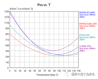
Magnetic loss curve
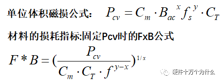
Core Bmax Selection Method
f
f*B: Ability to express B that a material can pass at one frequency
A. Increased frequency, the ability of magnetic energy materials to pass power
B. Frequency increases to a certain degree, there will be a better high frequency material to take over
Under normal circumstances, it must be designed to ensure that Bm (Maximum Flux Density) is less than or much smaller than Bs (Saturation Flux Density), and that the working flux density is any value between -Bm and Bm. Special circumstances, there may be Bm = Bs
Under normal circumstances
Fs<150KHz, Bmax depends on Bs,
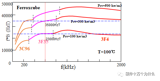
Assuming fs=100KHz, taking 80% of Bs as a benchmark, material 3C96, Bmax=0.5*80%*Bs=136mT
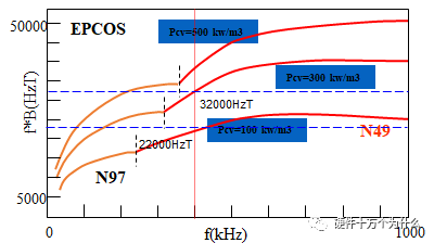
Fs>300KHz, Bmax depends on the magnetic loss Pcv
Assume that the frequency fs = 400KHz, take the unit magnetic loss is 300mw/cc, material N49, Bmax = 32000HzT/400KHz = 80mT
When fs is between 150K and 300K, both Bs and Pcv are taken into consideration, whichever is smaller.
Suppose frequency fs=200KHz, material 3C96, Pcv<300mw/cc
B1=0.5*80%*Bs=136mT; B2=28000HzT/200KHz=140mT,
Take the small value in B1 and B2 as Bmax=136mT
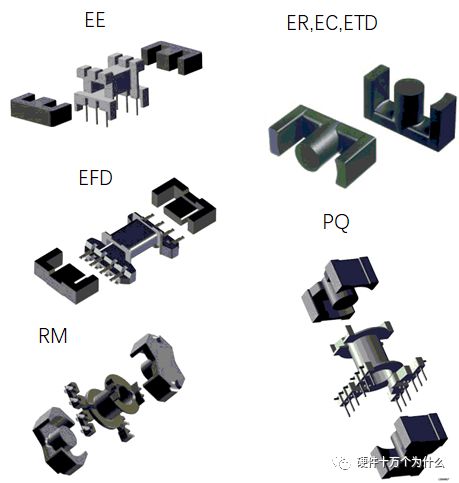
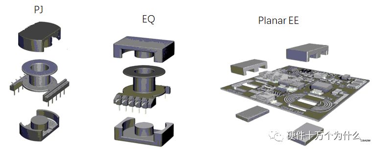
Select the shape of the core
| Shape classification | Features | Applicable |
| EE, ER, EC, ETD | Conventional core, low price, large window area, easy to make safety regulations at high power. | Low-power auxiliary power supply, high-power power supply, For applications with low power density |
| EFD | Plane EE core | Applications as above, applied to low power density, and require Low Profile, surface mount or settlement type structure |
| PQ, RM | The window area is smaller than the EE class, while Ae is larger than the EE class. | Applied to high power density conditions. Also suitable for use as an output inductor or PFC inductor. Small window openings, uncomfortable with many output transformers |
| Shape classification | Features | Applicable |
| PJ | Improved version of POT Core, Ae has a small window, good magnetic shielding effect, and a low height | Transformer design for high power density and high altitude requirements; not suitable for flying wires, not suitable for use with Margin tape |
| EQ | PJ, PQ improved version, window conditions better than PJ, height and Ae better than PQ; magnetic shielding effect is not as good as PJ | |
| Planar EE | Low height, large Ae, small window; large center-to-width ratio, not suitable for winding | Transformers and inductors for prefabricated windings such as PCB windings |
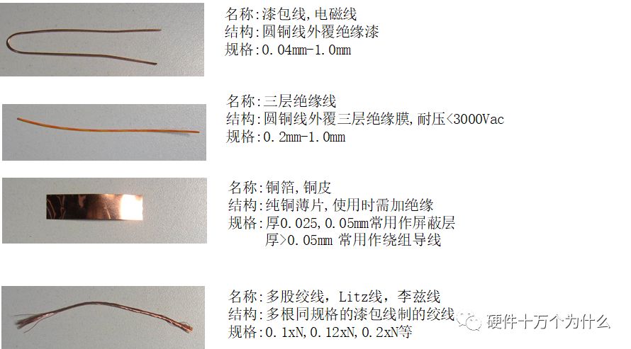
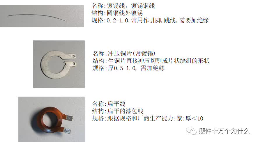
wire:
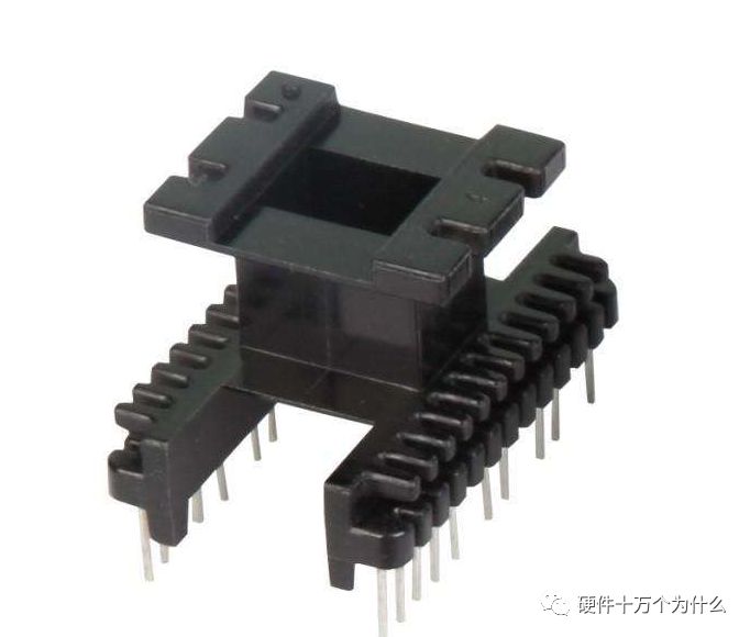
Bobbin:
As the name suggests, Bobbin (wire rack or skeleton) plays the role of supporting Coil in the transformer.
Bobbin's classification:
1, according to the different nature of the transformer requirements, according to the material is divided into: thermoplastic materials, thermosetting materials.
Thermoplastic materials We use nylon (NYLON), plastic (PET), plastic (PBT) three kinds. heat
Solid materials We often use bakelite (PM).
2, according to the shape of the transformer, Bobbin is divided into vertical, horizontal, child-type, drawer type, cell, double grid.
Features and uses:
1. Bakelite (PM): thermosetting material, high stability, not easily deformed, temperature 150 °C, can withstand high 370 °C
temperature. The surface is smooth, fragile and cannot be recycled. For higher temperature transformers.
2. Nylon (NYLON): thermoplastic material, engineering plastics, good ductility, non-broken, temperature 115 °C, easy to absorb water, use baking temperature of 80 °C before use, so that the stability of the solid. Smooth surface, translucent, non-friable. Generally used for transformers with strong oil resistance.
3, plastic (PET): thermoplastic material, 510 system, high rigidity, easy to form. It is not easy to be deformed and has a temperature resistance of 170°C. The surface is not smooth and it is not brittle. It is generally used for bobbins.
4, plastic (PBT): thermoplastic material, soft, not easily deformed, not resistant to high temperature (160 °C), the surface is not smooth, non-friable generally used for bobbin
5*20MM 6*30MM fuse holder fuse holder fuse holder
Suitable for 5.0 * 20MM fuse
Applicable current: 10A / 250V t-25 to t-70Material: insulator E130i UL 94-V0
Environmental protection products, certified by CE UL VDE CQC
Fuse (fuse), self recovery fuse (PPTC), ESD suppressor, etc.
It is widely used in a variety of electronic and electrical equipment, such as: computer and its peripheral equipment, LCD, battery pack, communication system, audio equipment, automotive industry, testing instruments, industrial control power supply and frequency converter, etc.
Fuse Holder
ShenZhen Antenk Electronics Co,Ltd , https://www.antenkelec.com