When the vehicle driving motor adopts decentralized driving, the unsynchronized speed of the motor may cause uncoordinated operation of the vehicle body, which may cause the speed of the motor to deviate from the normal value, which may cause equipment damage in severe cases. Therefore, it is of practical significance to solve the problem of motor speed asynchronization caused by decentralized driving of vehicle drive motors. This article introduces an advanced and practical control method that uses PLC to solve the motor speed synchronization when the vehicle is distributedly driven. At present, the operating equipment of vehicles generally adopts two methods of centralized driving (see Figure 1) and decentralized driving (see Figure 2). The relationship between the centralized drive inverter and the motor is "one dragging more"; when the drive is decentralized, the relationship between the two is "one dragging one". Figure 1 Illustration of centralized drive arrangement The advantage of "more dragging" is simple control and easy operation and maintenance, but the centralized driving arrangement requires a larger space for the car body. When the vehicle load is large or the space of the vehicle body is limited, the "one-for-one" decentralized driving method is usually adopted because of its compact structure and simple layout. However, "one-for-one" has high requirements on the inverter and the motor, especially the synchronization problem is difficult to solve. If the motor speed is inconsistent, the inverter will work in reverse, and the output current is too large, causing a trip, affecting the vehicle's working efficiency and the service life of electrical equipment. If the speed deviation is too large, it will cause deformation of the car body and affect its use. Adopt PLC and inverter control method to realize the synchronous operation of multiple decentralized drive motors. PLC adopts Siemens S7400 series. Figure 3 shows the network topology. In order to achieve the speed synchronization of the two traction motors, two frequency conversion motors are used for traction, and the frequency converters are used for vector closed-loop control, and the PLC is used to directly control the two frequency converters. In the control, Profibus connection is used between PLC and inverter to ensure the synchronization of the output signal source. Taking the speed of traction motor 1 as the target speed, the inverter of traction motor 2 adjusts its speed to track the speed of traction motor 1. The two incremental rotary encoders are coaxially connected to the motor, so that encoder 1 and encoder 2 respectively collect the speed pulse signals of the two motors and send the signals to the high-speed counting module of the PLC. The PLC uses these two speed signal data as input control variables to perform proportional integral control calculation (PID), and the calculation results are sent as output signals to the analog module of the PLC to control the inverter of the traction motor 2. In this way, it is possible to ensure that the speed of the traction motor 2 tracks and changes as the speed of the traction motor 1 changes. Keep the two speeds in sync. The pulse signal collected from the encoder enters the PLC through the high-speed counting module FM350-1 and is converted into motor speed data. Compare the signals of the two motor encoders and adjust the difference in motor speed through the PID adjustment module to give the motor 2 speed value. It needs to be converted into a signal that the inverter can accept. Since the corresponding 4-20mA value of PLC is 0 ~ 27648, and the receiving range of the inverter is 0 ~ 8192, so / 27648 × 8192 is sent to the analog output channel, converted into a current signal that the inverter can accept to control the traction motor 2 Inverter, PID algorithm is the most commonly used mathematical algorithm in industrial control, the basic formula is as follows: Pou (tt) = Kp × (et) + Ki × Σ (et) + Kd × [(et)-(et- 1)] In the formula: Kp- proportional adjustment coefficient. It is to reflect the deviation of the system in proportion. Once the deviation of the system occurs, the proportional adjustment immediately produces an adjustment effect to reduce the error. Ki-integral adjustment factor. The system eliminates the steady-state error and improves the difference. The strength of the integral action depends on the integration time. The smaller the constant TI, the stronger the integral action. Kd— Differential adjustment coefficient. The differential action reflects the rate of change of the system deviation signal, is predictable, and can predict the trend of the deviation change, so it can produce a leading control effect, which has been eliminated by the differential adjustment function before the deviation has been formed. In order to reduce the external interference caused by power system fluctuations and other factors, when formulating the control algorithm, it is necessary to consider the use of integral links, that is, using a continuous and stable input signal for a period of time instead of a certain instantaneous input signal for PID operation to eliminate accumulation The error makes the number of revolutions adjustable within a certain range. In this way, the traction motor 1 and the traction motor 2 can be well synchronized and the synchronization accuracy is high, thereby ensuring the stability of the running mechanism. Using STEP7 to compile the monitoring program of PLC host computer, Wincc collects the speed value and draws the curve. The data extraction interval is 15ms. In fact, the speed of traction motor 1 and traction motor 2 are the same, but in order to reflect the tracking and fluctuation of traction motor 2, they are specifically separated here. The top is the speed curve of traction motor 1, and the bottom is the speed curve of traction motor 2. (See Figure 4). When the speed of the traction motor 1 changes, the traction motor 2 can respond in time, track, and can quickly reach stability. Experiments show that the control method of PLC and frequency converter can achieve higher synchronization requirements, fast response and small speed fluctuation range. Figure 4 Speed ​​curve of traction motor This control method has been applied in various furnace vehicles. In practical applications, the effect of running synchronous starting is obvious, and the vehicle runs smoothly. Practice has proved that the use of PLC to solve the motor speed synchronization control method when the vehicle is dispersedly driven has a good application effect. It is an ideal speed control method, which meets the production process requirements, reduces equipment maintenance costs, and ensures the normal operation of the vehicle. The production efficiency and economic benefits are remarkable. With the wide application of PLC and inverter control methods, the reliability and flexibility of the transmission system for speed control will be better improved.
When people search gaming laptop, indicates that they need high performance 15 Inch Gaming Laptop, comes with big screen size, high cpu, large memory and storage, high resolution display, quality bigger 12000mAh battery, 2MP Camera, etc. 15 or 14 inch 500 Dollar Gaming Laptop, 10th generation laptop, 11th gen gaming laptop, 12th generation laptop, Laptop Intel Core I7, Intel I5 Laptop are the Top 10 Gaming Laptops. Every gamer want to buy Gaming Laptop with higher processors, big 8GB, 12GB, 16GB system memory ram, large Solid State Drive so that can handle or storage digital data at a high speed, 1920*1080 Full HD Slimmer screen provides user stunning vivid visuals, fingerprint reader, backlight keyboard, etc.
Nowadays 11th Laptop is the most competitive cpu, cause performance is better than 10th, but price is nearly same; besides, Solid State Drive cost 512GB is the most welcome and competitive one.
Of course, You can also contact us directly and share your exact requirements, so that we can send the right and valuable information quickly.
Gaming Laptop,Top 10 Gaming Laptops,500 Dollar Gaming Laptop,15 Inch Gaming Laptop,Buy Gaming Laptop Henan Shuyi Electronics Co., Ltd. , https://www.shuyioemelectronics.com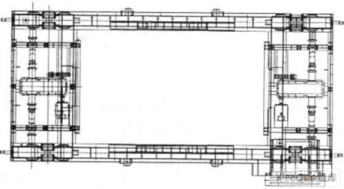

Figure 2 Schematic diagram of decentralized drive arrangement 
Figure 3 Network topology diagram 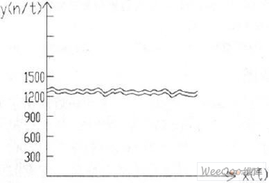
Using PLC to Solve the Problem of Synchronous Control of Vehicle Decentralized Drive 1 Introduction
October 09, 2024