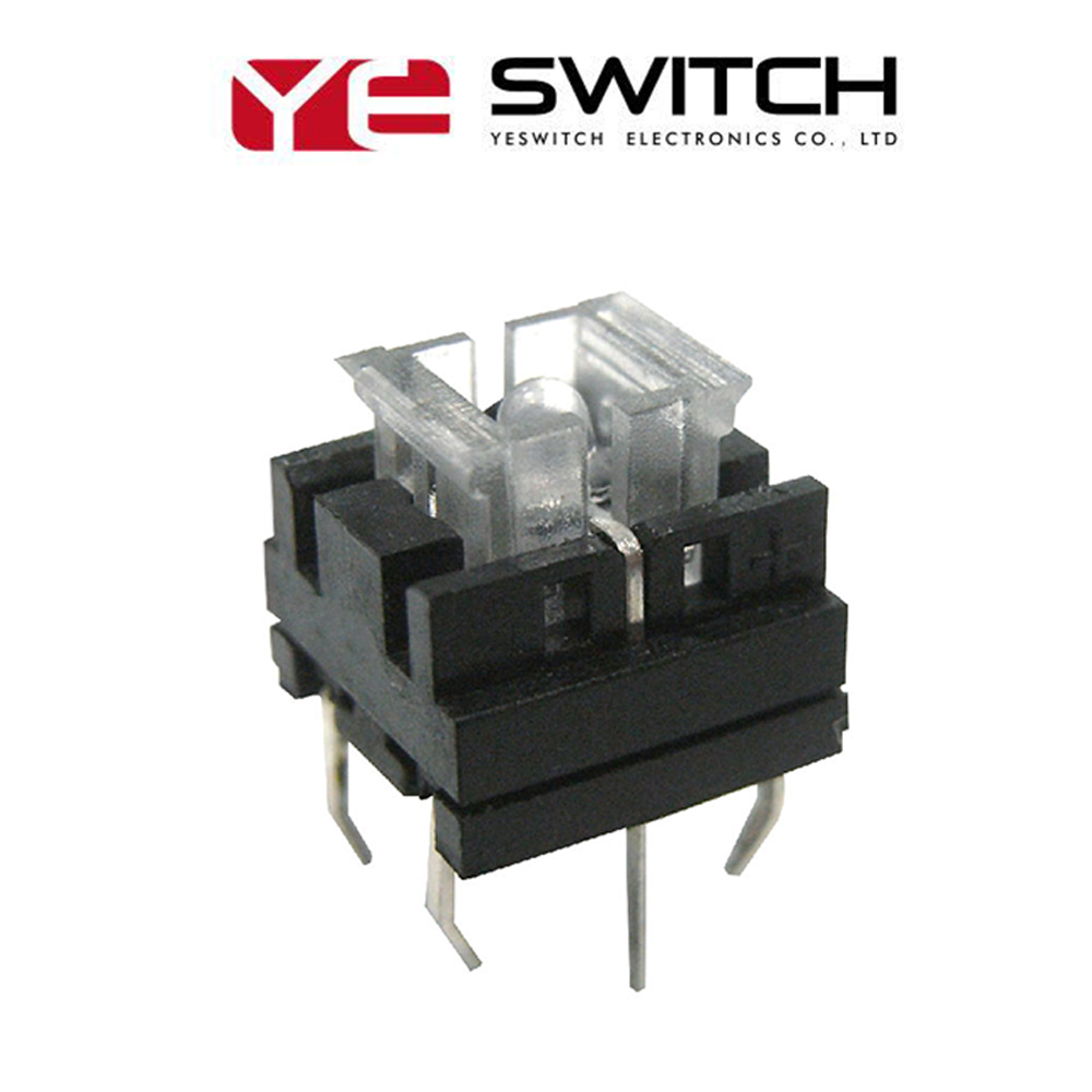
The Tact Switches, also called theTactile Push Button Switches, is used to meet the operating force to apply pressure to the switch operation direction. The switch function is closed and closed. When the pressure is released, the switch is opened, and the internal structure is realized by the force change of the metal shrapnel.
The Momentary Tact Switches has the advantages of small contact resistance, precise operating force error, and diversified specifications.We have a variety of Mini Tact Switches, including TK series, BP Series and other series. This Tactile Button offers many options on the item of circuit, comprising a single pole, single throw switch, or a single pole, double throw, double action switch.
This Push Button Switches that is PCB mounted and has a long travel. The distinctive feature is the double action of the double throw switch; It will actuates when press mid-travel and , then continue pressing for another actuation at full travel.
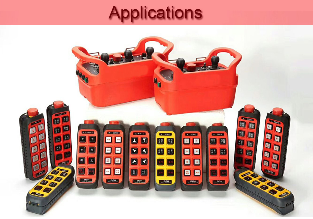
The applications of this Led Light Switches is including Audio and video products, digital products, remote controls, communication products, household appliances, security products, toys, computer products, fitness equipment, medical equipment, counterfeit pens, laser pointers, etc.
Tact Switches Micro Switches,Mini Switches,Micro Limit Switch,Micro Switches Types YESWITCH ELECTRONICS CO., LTD. , https://www.yeswitches.com
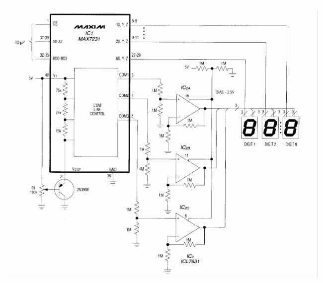
To conserve pins, many LCD Drivers triplex their drive signals—a technique that enables AC waveforms on trhree common lines and three segment lines to activate any standard character of a seven-segment display. Large LCDs of 1 "or more exhibit a large capacitance between the common and segment electrodes (several nonofarads), which presents a problem for standard LCD drivers.
These drivers' high output impedance (50KΩ, for example) causes difficulty in driving capacitance, and the consequent AC-Waveform distortioncan produce ghosting and shadow segments in the display. The drive circuit in Figure 1 solves this problem by introducing a buffer amplifier for each of the three common lines. Each amplifier may be programmed independently for a quiescent current of 10, 100 or 1000µA. In this application, the bias network applies a voltage that sets the three quiescent currents to 100µA.
The display driver and triple op amp operate between 5V and ground, and the COM signals range from 5V to ~ 1V. To assure that these signals remain within the amplifiers' common-mode range. We attenuate the signalsby one half and operate the buffers at a gain of two. The circuit drives eight 1 "displays and is suitable for ambient temperature variations of 15 ° F or less. At the highest expected temperature, you should adjust R1 so that no" off "segments are visible. 
Figure 1. Three buffer amplifiers enable this standard LCD driver (IC1) to control eight large (1 ") seven-segment displays."


Abstract: This applicaTIon notes shows how to buffer the triplex backplane drive outputs of a LCD driver such as MAX7231 family to increase the capaciTIve drive capability. This enables a large LCD to be driven without ghosTIng and other arTIfacts due to backplane waveform distortion.
May 13, 2020