18650 protected batteries have an electronic circuit.
The circuit is embedded in the cell packaging (battery casing) that protects the cell from [over charge", heat or [over discharge", over current and short circuit.
A 18650 protected battery is safer than an 18650 unprotected battery (less likely to overheat, burst or start on fire).
Batterie 18650, Battery Charger, CR123A Battery, 2032 Battery Shenzhen Powercom Electronics Co., Ltd. , https://www.expowercome.com
Note: This application note refers to the content of application note 3615. Application note 3615 can be downloaded.
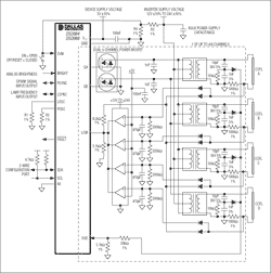
Independent lamp loop driving scheme Figure 1 details the scheme for driving multiple CCFL lamps per channel, as shown in Figure 1 in Application Note 3615. In this circuit, each CCFL lamp has an independent current return terminal, and the multi-channel CCFL controller detects the current flowing through the CCFL lamp on the low voltage side of the lamp. 
Detailed circuit (PDF, 153kb)
Figure 1. Using a separate lamp current return
The biggest advantage of this driving scheme is that it can accurately measure the lamp tube current and is not affected by the internal parasitic capacitance of the system. The current of the parasitic capacitance on the high-voltage side of the transformer secondary coil will be shunted before entering the lamp. In this circuit, all the current flowing through the parasitic capacitance does not pass through the feedback resistor, so the feedback resistor (1000Ω 1% shown in Figure 1) can accurately measure the current flowing into the lamp. The biggest disadvantage of this circuit is that each lamp requires an independent return path (or current detection line). Driving scheme of multiple lamps sharing the return end Another driving scheme is to detect the lamp current of the low voltage side of the transformer secondary coil, see Figure 2. In this driving circuit, all lamps share the same common ground at the far end or have the same current return terminal. This circuit configuration can reduce the system cost, but the detected lamp current includes the current flowing through the parasitic capacitance, or a part of the detected current does not flow into the lamp. 
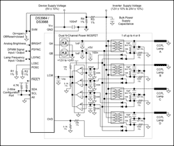
Detailed circuit diagram 2. Multiple lamps share the same current return
The CCFL driving circuit where multiple lamps share the same current return terminal is somewhat different in specific operations. The following table gives some suggestions: RecommendaTIon Reason 1. Use a transformer with a low side secondary connecTIon that is not close to the primary connecTIons. The switching impulses of the MOSFET can be easily coupled onto the feedback components and cause stability problems. 2. Route the ground connecTIon for the over-voltage capacitor divider through the lamp current feedback components. Reduces the affect of the over-voltage capacitor divider on the feedback measurement. 3. Keep the over-voltage capacitor divider at a ratio of about 100: 1. This will require the use of an additional resistor divider (33k and 5.1k in Figure 2) to properly set the voltage at the OVD input. To reduce the affect of grounding the over-voltage capacitor divider through the lamp current feedback resistor. 4. Include a low pass filter (15k ohms and 120pF in Figure 2) on the lamp current monitor feedback. To reduce the some of the high frequency energy created by the parasitic capacitance from influencing the lamp current feedback.
Adjust the lamp current. Because the current flowing through the feedback resistor includes the actual current flowing through the lamp and the current of the parasitic capacitance, the lamp current feedback resistor divider (15.0k and 5.11k resistors in Figure 2) needs to be based on the specific situation. Make adjustments. It is best to choose the appropriate ratio of resistance voltage division through experiments. For easy testing, a small resistor (100Ω) can be connected in series on the low voltage side of the lamp to measure the actual lamp current. Adjust the resistor divider after measuring the lamp current.
To prevent erroneous lamp ignition failure detection In a single-channel drive circuit that drives multiple CCFLs, the comparator is used to detect failure conditions such as lamp ignition failure or lamp open circuit. For more information, please refer to Application Note 3615. The parasitic capacitance in the system may generate a large peak voltage, which is sufficient to exceed the 5V lamp ignition / open circuit threshold of the comparator monitoring each lamp. Choose the appropriate lamp feedback resistor carefully to ensure that when no lamp is connected, the parasitic capacitance will not generate a voltage higher than the 5V lamp open detection threshold. Experiments show that for the circuit shown in Figure 2, when the lamp current is rated at 5mARMS, using a 1000Ω lamp feedback resistor can leave enough margin.
Abstract: DS3984 and DS3988 are multi-channel cold cathode fluorescent lamp (CCFL) controllers. DS3984 supports four channels, DS3988 supports eight channels. These controllers use a push-pull drive architecture to convert the DC power supply Voltage into the AC high-voltage waveform required to drive the CCFL. Application note 3615 describes a solution for driving multiple CCFL lamps per channel, each with an independent return. This application note explains the issues involved when changing the independent return end of a single-channel driven multi-lamp solution to a common return end for multiple lamps.
May 16, 2020