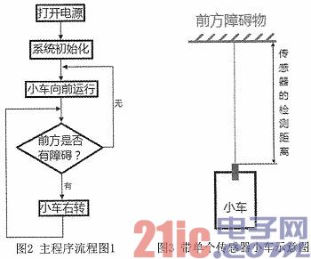
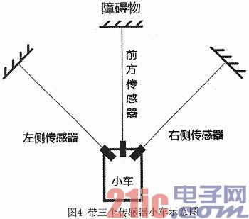
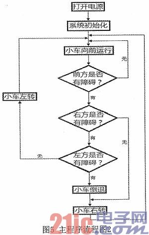
0 Preface This article refers to the address: http:// The emergency obstacle avoidance of the car is simulated by the driver's active control process. The real-time signal acquisition, analysis and processing are carried out by the car as the control object, which can replace the driver's driving operation in an emergency. The infrared sensor can sense the driving environment of the car and realize the obstacle avoidance function of the car. This paper designs a smart car controller based on embedded system through s3c44b0x development board and ADS integrated development platform. The advantages are low power consumption, small size, high integration and high reliability, which provides a broad prospect for the development of smart car technology. 1 System function description Ordinary toy cars generally need to be able to automatically follow the obstacles in front of them according to their own assumptions. At present, the embedded technology can be used to make the car intelligent without any additional conditions, that is, to achieve automatic avoidance of obstacles. The function. In principle, it mainly relies on the infrared obstacle avoidance sensor on the trolley to detect the signal of the obstacle that may appear and feed it back to the control circuit. When the sensor detects an obstacle, the sensor generates a high level signal. Driving a stepping motor on one side causes the cart to smoothly rotate and then proceeds forward. 2 system hardware design The hardware part of the overall design is shown in Figure 1. The development platform selected in this design is the ADS integrated development environment, and the hardware design and debugging work is carried out through the s3c44b0x chip related tool tftp. The infrared sensor is a device that can detect infrared rays and converts the amount of infrared radiation into a change in the amount of electricity. The performance of the infrared obstacle avoidance sensor GP2YOA02YK used in this design is as follows: 1) Reflectance: has a small influence on the color of the reflective object. 2) The analog voltage value returned by the sensor corresponds to the measured distance value. 3) Range of detection distance: 10 to 60 cm. 4) No external control circuitry is required. The DC motor drive module selected in the hardware design is a special driver for medium and small current DC motors. The chip 1293 used is an H-bridge integrated circuit. Its output current is 1000mA, the maximum current is 2A, and the maximum working voltage is 36V, which can drive inductive loads, such as small DC motors. , relays, stepper motors and switching power supply transistors. When driving a small DC motor, you can directly control the two motors, and can realize the forward and reverse rotation of the motor. To achieve this function, you only need to change the logic level of the input. The drive module has the characteristics of small size and convenient control. Test experiments show that this module can control the motor smoothly and reliably. 3 system software design The system software design is completed under the integrated development environment ADS and Microsoft Vistlal C++6.0 integrated development platform, mainly using C language for programming. Software design mainly includes the design of programs that control main programs, motor drivers, interrupt programs, and software algorithms. In the initial stage of the overall design of the system, an infrared obstacle avoidance sensor is installed directly in front of the smart car system, through which the obstacle signal from the front is collected and then transmitted to the control system, and the control system further takes action according to the signal. Controls the operation of two stepping motors. After a set time delay period, the main program operation continues to cycle until the power is turned off or the system fails. The main program flow chart of the car is shown in Figure 2. The initialization process includes the initialization of the ARM microprocessor and the initialization of the external drive circuit. Figure 3 is a schematic diagram of the use of a single sensor for a car. 4 System in-depth design outlook After the system design uses a single sensor to design the intelligent obstacle avoidance car, the next step is to use three sensors to design a smart obstacle avoidance car with more complete functions and more stable system. Figure 4 is a schematic view of a trolley using three infrared obstacle avoidance sensors. In the figure, the three sensors are located on the left, middle and right sides of the trolley, and can detect obstacle signals from the left, the front and the right. For this hardware frame design, the corresponding main program flow chart is shown in Figure 5. The benefits of the three sensors detecting obstacles in three directions are obvious, because they can maximize the "field of view" of the intelligent obstacle avoidance car, but at the same time there are some problems, such as the detection between the three sensor scanning ranges. The district is a relatively big injury to the smart car. Therefore, in the following design, we will further study and analyze the problems such as these, and strive to enrich the design of the car system without affecting the basic functions of the smart car. 5 Conclusion Due to the board, the board has eighteen design functions. In this test, one of its functions is to generate a pulse for controlling the DC geared motor. The system is simple in design, easy to implement in software programming, good in real-time and low in cost. Although there are some errors in the detection of obstacles by the infrared sensor, it does not affect the obstacle avoidance of the car. In an indoor environment, the car can smoothly bypass obstacles to the designated location. However, due to the angle problem of the infrared detector and the width of the vehicle, the trolley cannot completely avoid obstacles when the obstacle is large, so the trolley cannot fully realize the intelligence because the information obtained by the sensor is very limited, and the stepping motor is The impact of the control being driven is also uncertain. In terms of program firing, due to technical or method reasons, the program may sometimes be automatically deleted after firing. In general, the experiment was successful because the functions required before the experiment were basically achieved.
The Power Quality Module analyzes power quality event and disturbance data as well as power factor measurements. The module can also analyzes power quality event and disturbance data as well as power factor measurements based on the hierarchy sites, which are assigned to a user group.
Power Quality Module,Power Igbt Module,Power Amplifier Module,Power Supply Module Jiangsu Sfere Electric Co., Ltd , https://www.elecnova-global.com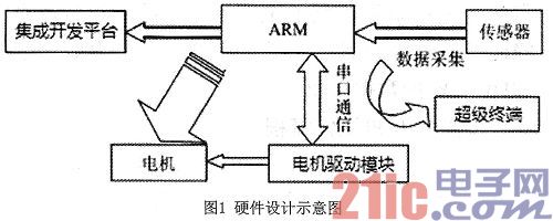
May 17, 2024