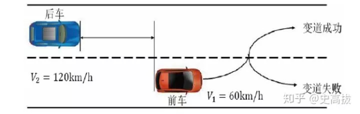
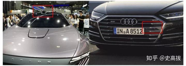
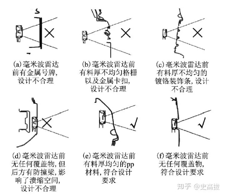
In "How to arrange the sensors of self-driving cars?" 》Dr. Wang Di of Xijiao analyzed the problem of sensor placement from the perspective of scientific research. In this article, the intelligent networked vehicle architecture engineer Shi Gaoba analyzed the sensor arrays of autonomous vehicles that can be mass-produced for us. Autonomous driving is one of the most cutting-edge research fields in the automotive industry. At this stage, only a small number of mass-produced cars have L2 level autonomous driving technology, and those that can reach L3 level are even rarer. However, the future development direction of the car is unmanned driving and autonomous driving, and to reach the L5 level, it will still require many years of hard work by engineers. When talking about unmanned driving, have you ever thought about how the related sensors will be arranged? What considerations need to be made? In today's article, Shi Gaoba, a KOL from Zhihu, an intelligent networked car architecture development engineer of a certain brand, will explain his views on how to arrange the sensors of autonomous vehicles from his perspective. Let me briefly discuss the considerations of sensor selection and layout for automated driving to be mass-produced. We all know that unmanned driving currently mainly uses several types of sensors such as cameras, millimeter wave radar, ultrasonic radar, and lidar. The characteristics of these types of sensors are different, as shown in the following table: It can be seen that the range and distance of various sensors are different, and some powerful sensors have high costs and relatively few options. How to reasonably select and arrange sensors has also become the key to autonomous driving research and development, especially mass production (cost issues). Typical area division According to the different situations encountered by the vehicle in different directions, the perception area around the vehicle can be divided into the following five types of areas: forward A, front side B, rear side E, rear D, and side C. Each area will encounter different situations in the driving of the vehicle, so in different areas, the requirements of the sensing range are different. For example, the forward area A is the most important area, which should cover the longitudinal safety distance when driving at full speed, while the B and E areas mainly detect the situation of adjacent lanes and the situation of turning. The main area where the sensor works Consider the needs of different usage scenarios Before the realization of L5 fully automatic driving, all automatic driving functions will restrict the scenes, such as highways or urban roads, low speeds or high speeds...Different scenes have different requirements for sensors. For example, highway scenes only need to identify vehicles, while urban roads also need to identify bicycles, electric vehicles, pedestrians, etc.; to ensure safety at high speeds, the detection distance must be farther than low speeds. Even in the same usage scenario, different functions have different requirements for sensors. For example, to realize automatic parking, you can rely on close-range ultrasonic radar and panoramic sensors. To realize the functions of AEB automatic emergency braking and ACC adaptive cruise on the highway, only the vehicles in the A area need to be detected; but if the lane change function is realized, the B and E areas may also need to be detected. And if the high-speed lane change also involves the scene of changing from a low-speed ramp to a driving road, there are more factors to consider. Examples of special scenarios For the above special scenarios, a simple example is given below (discussed by examples, not for actual reference): In the following scenario, the vehicle in front is driving on the ramp at a speed of 60km/h and needs to change to the normal driving lane. At this time, there is a 120km/h vehicle behind the target lane, and the time interval τ=2s, assuming that the lane change requires The time is 3s. Then the safe distance to the rear vehicle can be obtained as: Therefore, the sensor in the E area should be able to detect the distance of 83 meters behind the side to be safer, so the 24GHz millimeter wave radar (≤60m) cannot meet this requirement; you need to choose the 77GHz millimeter wave radar or the mid-range camera (Tess Pull Autopilot 2.0 program). There are many similar special scenes. Therefore, under the current existing technical conditions, it is necessary to sort out the use scenes first, and then design the sensor scheme according to the scenes and functions. Sensor redundancy The safety and reliability of autonomous driving have always been the most important considerations. If the design and development are only for the realization of functions, it is difficult to meet the demand for mass production. Therefore, for important functions in autonomous driving, redundant design and layout need to be considered. For example, in the important forward A area, in addition to the commonly used cameras, a millimeter-wave radar with a similar detection distance should also be arranged; ensure that if the camera fails or the camera is restricted, the millimeter-wave radar can still continue to a certain extent. Detection work. Tesla millimeter wave radar layout location The appearance of the sensor There will be more and more sensors in automobiles in the future. Sensors such as lidar and cameras cannot be blocked in any way. If the sensor is too large and has an unsightly appearance, it will not be accepted by the market willingly; therefore, the sensor is designed and arranged. Try not to affect the appearance is also an important consideration. Byton and Audi lidar layout comparison Millimeter wave radar layout Unlike sensors that rely on optics, millimeter-wave radar can theoretically be hidden and arranged (it is best if it is not blocked), but there are several basic principles that should be paid attention to when designing the cover and choosing the location of the arrangement: ①It is preferred to use materials with low electrolyte conductivity such as PC, PP, ABS, and TPO. Metal and carbon fiber cannot be sandwiched in these materials. ② The surface of the covering must be smooth and uniform in thickness, without sudden changes in material thickness or complex structure, and the thickness should preferably be an integer multiple of radar half-wavelength to reduce distortion and attenuation of radar waves. Schematic diagram of millimeter wave radar layout to sum up There is still room for improvement in current sensor technology. Sensors relying on optics, images, etc. cannot adapt to a variety of complex environments and scenarios; relying on the fusion algorithm of the perception system and combining the advantages of various sensors can expand the use of autonomous driving. . With the application of high-precision maps, V2X and other technologies, scenes beyond the detection distance of the sensor and scenes that cannot work due to weather will also be better covered. HYAKKI Vape,HYAKKI Vape 2500Puff,Hyakki Fragrant Mango,HYAKKI Disposable Vape,HYAKKI Vape Kit,HYAKKI Vape Pod TSVAPE Wholesale/OEM/ODM , https://www.tsecigarette.com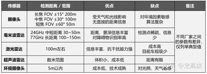


June 26, 2023