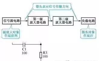
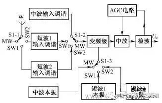
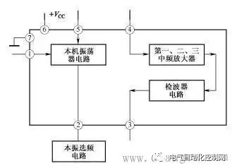
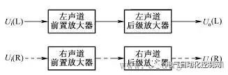
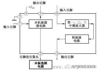
A preliminary understanding of electronic circuit diagrams Figure 1 shows an example of a simple electronic circuit diagram. Electronic circuit diagrams are used to represent the composition, structure, nominal value of components and other information of actual electronic circuits. As can be seen from this circuit diagram, the circuit consists of resistors R1-R3, capacitors C1-C3 and triode VT1 and other components. The connection line between the components indicates the connection relationship between the components in this circuit. The 270k below R1 represents the nominal resistance of the resistor, and the 100 below C1 is the nominal capacity of the capacitor. The unit indicates that the unit is pF, and the 2SC536 below VT1 is the model of the triode. Figure 1 Schematic diagram of electronic circuit diagram Understanding the types of circuit diagrams and mastering the basic analysis methods of various circuit diagrams is the first step in learning the working principles of electronic circuits. There are six main types of electronic circuit diagrams. (1) Block diagram (including circuit block diagram of the whole machine, system block diagram, etc.). (2) Unit circuit diagram. (3) Equivalent circuit diagram. (4) Integrated circuit application circuit diagram. (5) The circuit diagram of the whole machine. (6) Printed circuit board diagram. Block Diagram Recognition Method Figure 2 shows a block diagram of a two-stage audio signal amplification system. As can be seen from the figure, this system circuit is mainly composed of a signal source circuit, a first-stage amplifier, a second-stage amplifier and a load circuit. It can also be known from this block diagram that this is a two-stage amplifier circuit. Figure 2 Schematic diagram of block diagram There are many types of block diagrams, and there are mainly three types: the block diagram of the whole machine circuit, the block diagram of the system circuit and the block diagram of the circuit in the integrated circuit. 1. The circuit block diagram of the whole machine The circuit block diagram of the whole machine is a block diagram that expresses the circuit diagram of the whole machine, and it is also the most complicated block diagram in many block diagrams. Regarding the circuit block diagram of the whole machine, the following points are mainly explained. (1) From the circuit block diagram of the whole machine, we can understand the composition of the whole machine circuit and the relationship between each part of the unit circuit. (2) In the circuit block diagram of the whole machine, the connection lines with arrows are usually used to connect each unit circuit. Through the directions of these arrows in the figure, you can also understand the transmission of signals between the unit circuits of the whole machine. way etc. (3) The block diagram of the whole machine circuit of some machines is more complicated, some use a block diagram to represent the circuit structure of the whole machine, and some divide the block diagram of the whole machine circuit into several sheets. (4) Not all the complete machine circuits are given the block diagram of the complete machine circuit in the atlas data, but the block diagram of the complete machine circuit of the same type of complete machine circuit is basically similar, so taking advantage of this, you can use the Other complete machine circuit block diagrams to understand the circuit composition of the same type of complete machine. (5) The circuit block diagram of the whole machine is not only useful information for analyzing the working principle of the whole machine circuit, but also the basis for logical reasoning and establishment of correct maintenance ideas in troubleshooting. 2. System circuit block diagram A complete machine circuit is usually composed of many system circuits. The system circuit block diagram is used to represent the composition of the system circuit in the form of a block diagram. It is the block diagram of the next level of the complete machine circuit block diagram. The circuit block diagram is more detailed. Figure 3 shows a block diagram of the radio circuit system in the combined audio system. Figure 3 Block diagram of the radio circuit system 3. The circuit block diagram of the integrated circuit The circuit block diagram of the integrated circuit is a very common diagram. The composition of the internal circuit of the integrated circuit can be represented by the internal circuit block diagram. Because the integrated circuit is very complex, in many cases, it is more convenient to use the internal circuit block diagram to represent the internal circuit composition of the integrated circuit. From the block diagram of the internal circuit of the integrated circuit, we can understand the composition of the integrated circuit, the function of the pins and other identification information, which is very useful for analyzing the application circuit of the integrated circuit. Figure 4 shows a block diagram of the internal circuit of a certain type of radio amplifier integrated circuit. Figure radio mid-amp circuit block diagram It can be seen from the block diagram of the circuit in this integrated circuit that the circuit in the integrated circuit consists of a local oscillator circuit, a first, second and third stage intermediate frequency amplifier circuit and a detector circuit. 4. Block Diagram Function The function of the block diagram is mainly reflected in the following two aspects. (1) Expresses a lot of information. Roughly expresses the composition of a complex circuit (it can be a complete circuit, a system circuit, a functional circuit, etc.), usually giving the location and name of the main unit circuit of the complex circuit, as well as the breakthrough points of each electronic circuit. The connection relationship between unit circuits, such as the relationship between the previous stage and the subsequent stage, etc. (2) The direction of signal transmission is expressed. The block diagram expresses the signal transmission direction between each unit circuit, so that the reader can understand the transmission order of the signal between each part of the unit circuit; according to the circuit name marked in the block diagram, the reader can know that the signal is here. The processing in a unit circuit provides instructive information for analyzing specific circuits. For example, the block diagram shown in Figure 4 gives such identification information: the signal output by the signal source is first added to the first-stage amplifier for amplification (the direction of the arrow between the signal source circuit and the first-stage amplifier indicates the signal transmission direction ), and then sent to the second-stage amplifier to amplify, and then stimulate the load. important hint A block diagram is an important circuit diagram, especially when analyzing the application circuit diagram of an integrated circuit, a complex system circuit, and understanding the circuit composition of the whole machine. Without a block diagram, it will bring a lot of inconvenience and difficulty to the identification of the diagram. 5. Characteristics of block diagrams The concept of block diagrams is proposed mainly for the needs of diagram recognition. Understanding the following characteristics of block diagrams is of great significance for diagram recognition and repair. (1) The block diagram is concise and clear, and it is easy to see the composition of the circuit and the transmission direction and path of the signal, as well as the processing process of the signal during the transmission process, such as whether the signal is amplified or attenuated. (2) Because the block diagram is relatively simple and logical, it is easy to remember, and at the same time it contains a large amount of information, which makes the block diagram more important. (3) There are concise and detailed block diagrams. The more detailed the block diagram is, the more useful information is provided for identifying the diagram. Among various block diagrams, the internal circuit block diagram of the integrated circuit is the most detailed. (4) The direction of signal transmission (represented by arrows) is often marked in the block diagram, which visually represents the transmission direction of the signal in the circuit, which is very useful for identifying the diagram, especially the circuit block diagram in the integrated circuit. It can help the reader to know whether a pin is an input pin or an output pin (this is known from the direction of the arrow on the pin). 6. Block Diagram Recognition Method Regarding the block diagram recognition method, the following three points are explained. (1) Analyze the signal transmission process. When understanding the signal transmission process in the circuit diagram of the whole machine, it is mainly to look at the direction of the arrow in the figure. The path where the arrow is located represents the transmission path of the signal, and the direction of the arrow indicates the transmission direction of the signal. In the block diagram of the complete circuit of some audio equipment, the signal transmission indication arrows of the left and right channel circuits are represented by solid lines and dashed lines, as shown in Figure 5. Figure 5 Schematic diagram of solid and dashed lines (2) Composition of memory circuit. When memorizing the composition of a circuit system, a block diagram is used because the specific circuit is too complicated. In the block diagram, you can see the relationship between each part of the circuit (how they are connected to each other), especially the control circuit system, you can see the transmission process of the control signal, the source of the control signal and the object of control. (3) Analysis of integrated circuits. In the process of analyzing the application circuit of the integrated circuit, when there is no information on the function of the pins of the integrated circuit, you can use the internal circuit block diagram of the integrated circuit to understand and reason about the specific functions of the pins, especially which pins are input pins. , which are the output pins, which are the power pins, and these three pins are very important to identify the map. When the arrow of the pin lead points to the outside of the IC, it is an output pin, and when the arrow points to the inside, it is an input lead. For example: in the block diagram of the integrated circuit shown in Figure 6, the arrow of pin ①of the integrated circuit is inward, which is the input pin, indicating that the signal is input from the pin ①to the frequency conversion stage circuit, so the pin ①is the input pin; ⑤ The direction of the arrow on the pin is outward, so pin ⑤ is the output pin, and the frequency-converted signal is output from this pin; pin 4 is the input pin, and the input is the intermediate frequency signal, because the signal is input into the intermediate frequency amplifier circuit, Therefore, the input signal is an intermediate frequency signal; the ③ pin is the output pin, which outputs the audio signal after detection. Figure 6 Schematic diagram of integrated circuit block diagram When there is no arrow on the lead, such as pin ② in the integrated circuit shown in Figure 6, it means that the relationship between the external circuit and the internal circuit of the pin is not a simple input or output relationship. There is a certain connection, and the second pin should be connected with the relevant components in the local oscillator circuit in the external circuit. The block diagram cannot express the specific connection, which is also a shortcoming of the block diagram. In addition, in the circuit block diagram of some integrated circuits, the arrows on some pins are bidirectional, as shown in Figure 7, this situation is common in digital integrated circuits, which means that the signal can be input from this pin, or can be output from this pin. Figure 7 Schematic 7. Precautions for block diagram identification The following points should be paid attention to when identifying the block diagram. (1) The circuit data provided by the manufacturer does not generally give the circuit block diagram of the whole machine, but most of the same type of machines have similar circuit composition. Using this feature, the whole machine block diagram of the same type of machine can be used as the refer to. (2) Under normal circumstances, it is not necessary to analyze the internal circuit of the integrated circuit, and it is only necessary to point to the input pin through the block diagram of the internal circuit of the integrated circuit. Understand the amplification and processing of signals in circuits within integrated circuits. (3) The block diagram is the circuit diagram that needs to be memorized first among many circuits. Remembering the block diagram of the whole machine circuit and the block diagrams of some other main system circuits is the first step in learning electronic circuits.
It is suitable for the computers.inspection appliance and instruments with rated voltage up to 300/500V. This product presents an excellent performance in high
frequency locations
Instrument Cable,Moving Rubber Cable,Cpe Sheath Flexible Cable,Outer Moving Cable Baosheng Science&Technology Innovation Co.,Ltd , https://www.bscables.com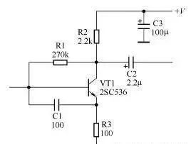
May 21, 2023