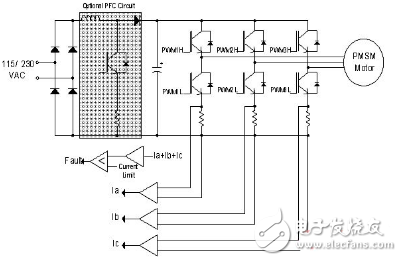
This paper begins with the use of DSC to implement FOC-based sensorless PMSM control. It mainly introduces how to implement sensorless FOC control based on permanent magnet synchronous motor (PMSM) in electrical appliances, so as to bring the most cost-effectiveness to electrical motor control. For some applications where position or speed sensors cannot be deployed, sensorless FOC technology can overcome some of the resulting limitations. For example, in some compressor applications, the motor full of oil can have some limitations on the harness layout. When a PMSM motor is used in an electric appliance, since the rotor magnetic field generated by the permanent magnet on the rotor of the PMSM motor is constant, extremely high efficiency can be provided. In addition, the stator magnetic field of the motor is generated by a sinusoidally distributed winding. Compared to induction motors, PMSM motors also have an extremely high power/size ratio. Like DC motors, they have lower electrical noise because they do not use brushes. DSCs are well-suited for appliances such as washing machines because they have peripherals tailored for motor control, such as pulse width modulators (PWMs), analog-to-digital converters (ADCs), and quadrature encoder interfaces. When executing the controller program and implementing the digital filter, the DSC can help the designer optimize the execution of the code because it can perform MAC instructions and fractional operations in a single cycle. In addition, for operations that require saturation, DSC provides hardware saturation protection to help designers avoid overflow. DSCs require fast and flexible ADCs for current sensing, a key feature in motor control. The Microchip dsPIC DSC family offers an ADC that can convert input samples at 1Msps and can process up to four inputs simultaneously. These ADCs feature a variety of trigger options to support the use of low cost current sense resistors to measure motor phase winding current. For example, A/D conversion can be triggered by the PWM module to support low cost current sensing circuits. At a specific time, the switching transistor allows current to flow into the sense resistor, which can be detected at this time. The FOC motor control firmware discussed in this article is based on Microchip's dsPICDEM MC1 Motor Control Development Board. The FOC algorithm is tested and debugged using Microchip's Data Surveillance and Control Interface (DMCI) tool, a module of the MPLAB Integrated Development Environment (IDE). The DMCI tool provides a fast, dynamic IDE that allows designers to graphically represent application feedback. For example, in the DMCI IDE, program symbols (variables) can be dynamically assigned to any combination of scroll bars, direct inputs, or Boolean controls, and the IDE provides project-aware navigation for these symbols (variables). These controls allow users to interactively change the value of a program variable in the DMCI IDE. In addition, users can dynamically configure graphics to view program-generated data. In the system block diagram (Figure 1), it can be seen that no position sensor is installed on the motor shaft, but some sensors are used on the motor to measure the current. These sensors have low inductive resistance and they are part of the inverter's functional modules. A three-phase inverter is used here as a power stage for driving the motor windings (Figure 2). Figure 1: USB interface dedicated charger. Figure 2: Three-phase inverter drives the PMSM winding. Brief steps for the FOC (or Vector Control) algorithm The following is a summary of the FOC algorithm steps that control PMSM. 1. First measure the three-phase stator currents ia and ib. The current from the two current sensors is calculated according to ia+ib+ic=0. 2. Convert the three-phase current into a 2-axis coordinate system. This conversion yields the variables iα and iβ based on the measured ia, ib and ic values. From the perspective of the stator, iα and iβ are time-varying quadrature current values. This step is called Park Transformation. 3. Rotate the 2-axis coordinate system with the transformation angle calculated at the last iteration of the control loop to align it with the rotor flux. This conversion yields the variables id and iq based on iα and iβ. Now, the orthogonal currents id and iq are transformed into a rotating coordinate system. Under steady state conditions, id and iq will remain constant. This step is called the Clarke transform. Agriculture Staple,604 Fixing Nail,Hardware Staples Nail,Custom Agricultural Use Nail Zhejiang Best Nail Industrial Co., Ltd. , https://www.beststaple.com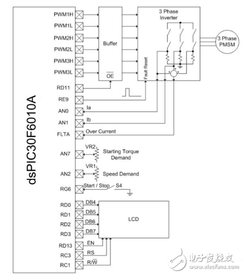
October 31, 2021