Overall effect: Follow WeChat Download Audiophile APP Follow the audiophile class related suggestion Friends who love electronic technology may be flipping through some e-books ... 3. Power supply and speaker protection circuit & nb ... Regardless of principle or practice, the advantages of electronic frequency division have been widely recognized. But why is it not widely promoted? I think there are two main reasons:
First, the effective frequency bands of different speaker units are different. A set of fixed electronic frequency dividers can only target a specific set of speaker units. This is similar to power frequency division. The difference is that: power frequency division The frequency divider has been installed in the sound box, forming a whole with the sound box without user adjustment; and the electronic frequency divider is inserted before the power amplifier, and the frequency division point needs to be based on the characteristics of the speaker unit Setting, so that the crossover, power amplifier and sound box together form a system, which is difficult for the user to adjust. Therefore, the electronic crossover with a fixed crossover point lacks universal applicability to the finished sound box. If the crossover point can be adjusted freely according to the characteristics of different speaker units, the scope of application of the electronic crossover will be greatly expanded.
Second, upgrading existing equipment to electronic crossover requires users to possess certain professional knowledge. If the electronic frequency divider can adjust the frequency dividing point simply by pressing the button like other equipment, and use the connector to connect, it can solve the problem of popularization and application.
Although electronic frequency division requires more power amplifiers and requires more investment, multi-channel power amplifiers are now very common. Although most of them are AV amplifiers, it can be seen that they are suitable for electronic frequency division. Channel Hi-Fi power amplifier, its price will not become the main factor restricting the popularization of electronic frequency division.
After long-term efforts, we have developed this set of electronic two-frequency pre-amplifiers, integrating source selection, high and low frequency independence, accurate crossover point adjustment, attenuation adjustment, phase adjustment, four-channel high-quality, high-reliability MOSFET High bias current Class A and B power amplifiers, multiple input and output are combined in a system, and the microprocessor is used to control the adjustment and display of the crossover point. See the photo of the head for the appearance.
One. Two-way preamplifier.
The pre-amplifier is an electronic two-frequency pre-amplifier, which is composed of an input selection and amplification circuit, a frequency division filter circuit, a microcontroller control circuit, and a power supply circuit.
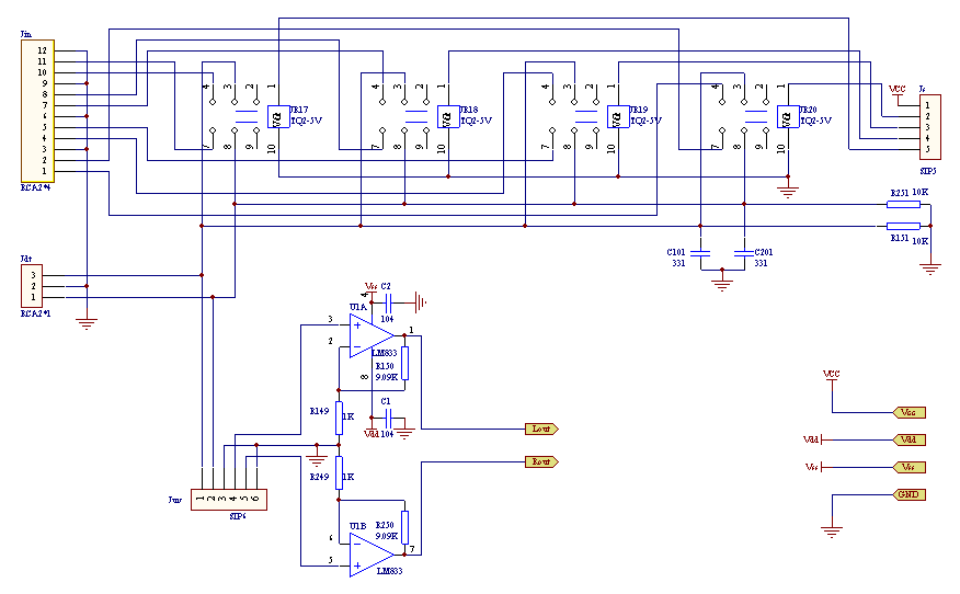
1. Input circuit The signal switching of the input selection part is composed of imported high-quality miniature signal relays JR17-JR20, and is controlled by a four-position band switch through the socket Js. This structure minimizes the length of the wire number line, the advantages are self-evident. Jin is a quad two-channel RCA socket, which can be connected to four stereo signals. The selected two-channel signal is divided into two channels: one channel is output through the RCA socket Jdt for "through" input or output, or an external subwoofer amplifier; the other channel is connected to the volume potentiometer through the socket JUV, and then input to the dual Put U1A, U1B to complete the pre-amplification, the magnification can be determined according to the needs, the value in the figure is 10 times. The output signal of the amplifier is directly sent to the frequency dividing filter circuit shown in FIG. 2. 
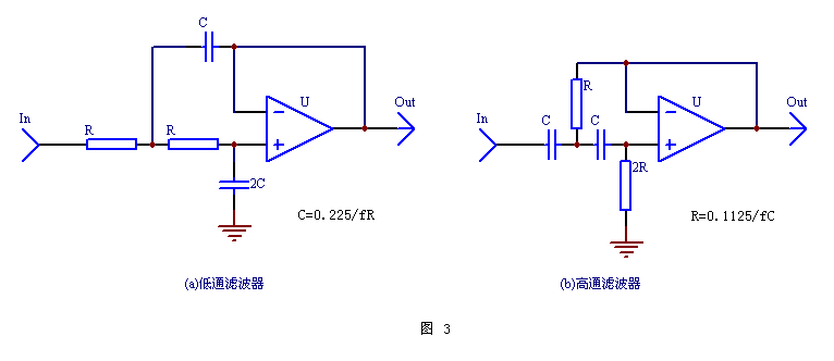
2. Frequency-dividing filter circuit After comprehensive consideration, the frequency-dividing filter circuit still selects a second-order Butterworth filter with both transient characteristics and attenuation characteristics. The basic circuit is shown in Figures 2a and b. Of course, you can also choose a Bessel filter with better transient characteristics, or a Chebyshev filter with better attenuation characteristics (the basic circuit is the same as Figure 2, but the resistance and capacitance values ​​are different. ). But the disadvantage of the Bessel filter is that the attenuation in the stop band is relatively small; second, the phase shift of the turning point is not 90 ° (for the second order), but 74.2 °, which is not conducive to the phase connection of the frequency division. ; Third, the capacitor value is more complicated. However, the Bessel filter's excellent transient characteristics and flat delay characteristics make it more used in low-pass filters in CD. Because the task of the low-pass filter in the CD is to completely filter out high-frequency components, without considering the problem of high-low frequency phase connection. The Chebyshev filter has steeper attenuation characteristics, but its transient and phase characteristics are slightly worse, and the attenuation rate in the passband has small ripple-like fluctuations, so it is only occasionally applied to active subwoofers. 
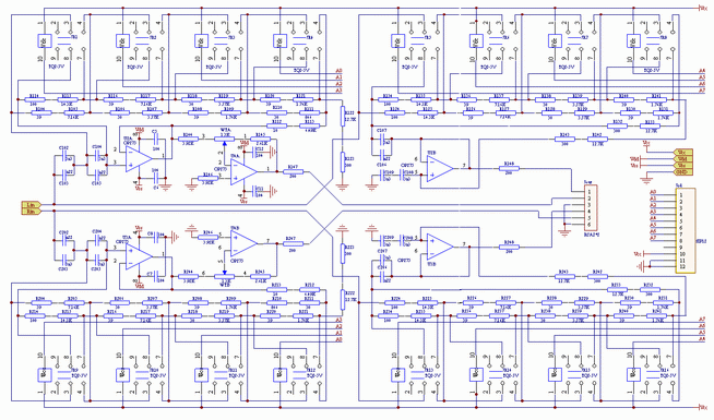
In Figure 2, the high-bass crossover of each channel uses 4 high-quality imported mini-signal relays to change the resistance of the filter network, so a total of 16 relays from JR1 to JR16 are used. . In each circuit, the filter resistor is connected between each group of moving contacts and normally open contacts of the relay, and the resistance is shorted or connected to the circuit by the pull-in and release of the relay, so that 4 relays have 2 4 = 16 This arrangement of pull-in and release produces 16 crossover points. All relays are controlled by the single-chip microcomputer in Figure 4 through 8 control lines A0-A7, where A0-A3 is used to control the crossover point of the left and right channel treble; A4-A7 is used to control the crossover point of the left and right channel bass. Since A0-A3 and A4-A7 are independent of each other, the crossover point of high and low bass can be adjusted independently. For example, the treble crossover point can be adjusted to 2.5kHz, while the bass is adjusted to 3.1kHz, so that there can be a 2.5-3.1kHz overlap area between high and low, and vice versa. This unique design is very convenient for audiophiles to test the listening characteristics of equipment, find problems or adjust equipment. The output ends of the left and right channel treble frequency-divided operational amplifiers U2A and U3A are respectively connected to the input ends of the reverse amplifiers U4A and U4B to form a treble attenuation network. In practical applications, the attenuation potentiometer WT (A, B) in the figure has been replaced by an attenuation network composed of a 2 * 6 band switch and a fixed resistance. The maximum resistance is the same as the potentiometer WT, which is passed through the PCB The connector Jt-adj access. Replace the potentiometer with a fixed resistor, the attenuation value can be clearly scaled, here is 0, -1, -2, -3, -4, -6dB, which is enough to adapt to the sensitivity of the high and low speakers in most sound boxes difference. U2B, U3B and their resistance-capacitance network constitute the bass crossover of the left and right channels, and the structure is the same as the treble part, which will not be described here. The high and low frequencies of the left and right channels are respectively output through the RCA socket Jout, and the resistors R147, R148 and R247, R248 play the role of isolation protection. Since the maximum point potential drift in the op amp is only a dozen mV, the circuits are all DC coupled to expand the system frequency response. 
Since most of the calculated resistance values ​​are not the standard values ​​in the 1% accuracy series, the resistors in the crossover network are formed by connecting two resistors in series to maximize the accuracy of the crossover point. The capacitance is also obtained in series and parallel in the same way, and the accurate value is obtained by measuring with a capacitance meter. The basic requirements for op amps are high input impedance and low output impedance. Here, OP275, which has a good reputation among enthusiasts, is selected here. 


![[Photo] Electronic constant current source](http://i.bosscdn.com/blog/20/06/41/523130482.gif)
![[Photo] Electronic frequency division preamp section](http://i.bosscdn.com/blog/20/06/41/513841338.gif)
![[Photo] Part 1 of electronic preamplifier](http://i.bosscdn.com/blog/20/06/41/513834375.gif)
![[Photos] The post-stage part of the electronic frequency divider before and after the amplifier (2)](http://i.bosscdn.com/blog/20/06/41/513441701.gif)
'+ data.username +'
Interesting and informative information and technical dry goods
Create your own personal electronic circle
Lock the latest course activities and technical live broadcast
comment
Publish
[Photo] Electronic constant current source
Posted at 2006-04-15 23:01 • 214 times read
[Photo] Electronic frequency division preamp section
Posted at 2006-04-15 13:08 • 715 views
[Photo] Part 1 of electronic preamplifier
Posted at 2006-04-15 13:08 • 1067 views
[Photos] The post-stage part of the electronic frequency divider before and after the amplifier (2)
Posted at 2006-04-15 13:04 • 641 views
