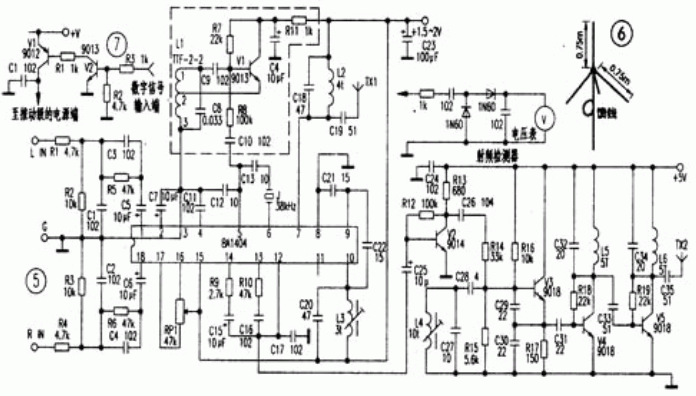
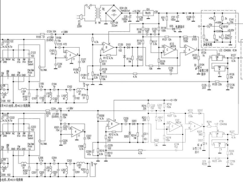
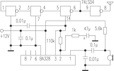
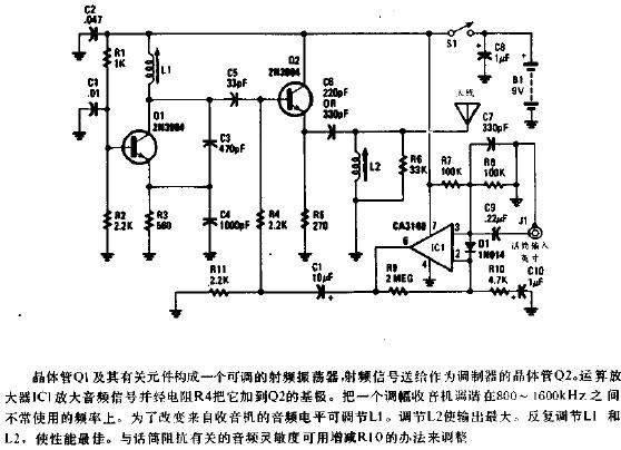
upc1651 FM wireless microphone Working principle As shown in the figure, the entire transmitter is composed of low frequency amplification, varactor bias, and oscillation circuit. After the audio signal is amplified by BG1, it is sent to the varactor tube, whose capacity changes with the signal, and the frequency of the oscillation circuit is directly modulated, eliminating the parasitic amplitude modulation phenomenon of the frequency regulation using the transistor junction capacitor, and the harmonic components are few. The frequency-modulated RF signal is directly radiated from L1 into space. Follow WeChat Download Audiophile APP Follow the audiophile class related suggestion This article introduces the circuit diagram details of seven wireless microphones. The electronic component microphone (microphone) on the circuit board first turns the natural sound signal into an audio electrical signal, ... This article introduces the wireless microphone circuit design and schematic diagram. The wireless microphone circuit consists of a sound pickup circuit, a sound conversion circuit, a high frequency oscillator, and modulation ... This article introduces the circuit diagram of four 9018 wireless microphones. The wireless microphone is composed of several pocket transmitters (which can be installed in the pocket and the output power is about 0.0 ... The wireless microphone is composed of several pocket transmitters (which can be installed in the pocket and the output power is about 0.01W) and a centralized receiver. Each pocket sends ... The V segment does interfere with each other when multiple sets of wireless microphones are used. Of course, it cannot be said that the U segment does not, but it has a large extension range and can be adjusted as much as possible ... In today's era of extremely rich material products and extremely active cultural life, many enterprises and institutions have many entertainment or group activities. in... Every electronic lover has the experience of electronic production, from continuous failure at the beginning to gradual handy, the taste is beyond the reach of outsiders ... R1 in the circuit diagram of the enhanced wireless microphone is the bias resistance of the microphone MIC, generally selected in 2K-5.6K. R4 is the collector resistance. Give here ... This article introduces in detail more than a few representative low-power transmitters in the 88 ~ 108MHz FM broadcast range that are easy to make in amateur situations ... The microphone works with a single tube, and the working voltage only needs 1.5V. The frequency is tuned in the FM band of 88 ~ 108MHz, and the ordinary FM radio is used ... Recently, some film and television sound workers have conducted detailed practical tests on several wireless microphones commonly used in daily work. The pickup of wireless microphone not only involves the distance ... If your recorder has FM reception band, you may wish to make a wireless microphone yourself, which can add a lot of fun to your life. The frequency changes. When assembling, the lead of the component should be soldered as short as possible. The wireless microphone rod pointer introduced in this article combines the FM wireless microphone and the portable rod pointer, and cleverly uses the metal part of the pointer as a word. The production of several wireless microphone circuits This article introduces in detail the representative ones that are easy to make successfully in amateur situations ... The principle and circuit of KMW-306 channel wireless microphone KMW-306 wireless microphone is a cost-effective electroacoustic used in karaoke and other dance halls ... The principle of wireless microphone production: The electronic component microphone (microphone) on the circuit board first turns the natural sound signal into an audio electrical signal, which ... The use of NAND gates to make wireless microphones and circuit wireless microphones can be seen everywhere on the market, but without exception, all use LC oscillators or quartz crystals ... The wireless microphone circuit made by the NAND gate circuit is available everywhere on the market, but the circuit is made of lc oscillator or quartz crystal oscillator circuit ... How to choose a wireless microphone Overview Due to the progress of today's radio communication technology, the quality and function of wireless microphone products have been relatively improved ... High-performance dual-band wireless microphone receiving circuit diagram Circuit diagram of amplitude modulation wireless microphone The circuit is shown in the figure, IC1, C1 form a low-frequency oscillator around 400HZ; IC2 ... The circuit is shown in the figure, IC1, C1 make up 400H ... The circuit shown in Figure 1 can transmit audio signals to remote locations in a frequency-modulated (FM) manner. & The wireless microphone circuit has a reasonable design, beautiful and elegant shape, long sound transmission distance, long service life, long ... A few days ago, the price of a wireless microphone on the market was between 10 and 20 yuan. The microphone is adjusted ... The circuit is shown in the figure. This circuit uses Japanese NE ... Electricity
The component selection inductor L1 is made of ∮1mm enameled wire wound around ∮8mm round tube for 5 turns, and the tire is hollow. L2 is made of enameled wire of ∮0.1 ~ 0.3mm around 100 turns on a 1 / 4W carbon film resistor with a resistance greater than 100kΩ, and the joint is welded to both ends of the resistor. Ceramic capacitors. The resistors are all 1 / 8W, 0.01μF decoupling capacitors can use ordinary ceramic capacitors.
For installation and debugging, it is recommended to use the corrosion method to make the circuit board. Solder the resistance and capacitance components first, and then solder the semiconductor components. After the soldering is completed, check the + 6V power supply, and measure the voltage of the 0.94 emitter to ground. If not, R1 should be adjusted. Re-measure the voltage of the emitter to the ground at 1-18V. If it is not correct, adjust R6, and then measure that the two poles of the varactor diode have no voltage, or the voltage difference between the two poles is less than 0.25V. If the pressure difference between the two poles is too large, R3 or R4 can be adjusted. After adjusting the above items, turn on the FM section of the radio, receive the signal emitted by the transmitter, and pull it away to a distance of more than 5 meters. If you cannot find the signal sent by the transmitter, you can adjust L1, stretch L1, the fundamental frequency rises, and compress L1, the frequency of the fundamental wave drops, so that the transmitter frequency can avoid the local radio station, and it can be received reliably. Then connect the output signal of the player and other equipment, carefully adjust W1, so that the music is not distorted at high volume (it is not allowed to turn the volume of the player and other equipment to the maximum, but at the commonly used volume position). After the adjustment of the above items, the commissioning is basically over. Put it into a sturdy plastic or wooden box (no metal box is available) and decorate it for listening to music or as a TV sound transmitter. It is the same as the FM radio signal. Clear and stable, it can be called an "amateur professional transmitter". And no antenna is needed, and the volume is small, because there is no need to worry about the transmission distance because it is used at home.
I used it as a TV sound transmitter, connected the audio input to the audio output of the TV, powered by a 6V battery, and used a crocodile clip as a switch. The circuit board is tied to the battery with a rubber band, which can be used continuously for tens of days without worrying about running out of power.
The transmitter is simple to manufacture, reliable in performance and low in cost. In the specific production, the circuit board used by the author is an epoxy board with low high-frequency loss. After debugging, each coil is made of high-quality high-frequency wax seal, and the effect is very good. The 5pF capacitor can be replaced by a double-sided copper-clad plate (calculated as 1pF = 1 mm2). 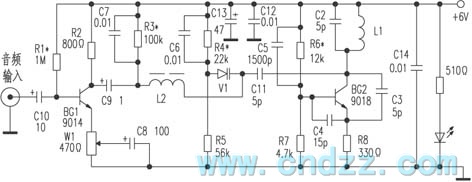








![[Photo] Multi-purpose signal generator made by UPC1651](http://i.bosscdn.com/blog/20/06/41/7191045673.gif)

![[Photo] Single tube wireless microphone](http://i.bosscdn.com/blog/20/06/41/5205848411.gif)
![[Photo] FM wireless microphone](http://i.bosscdn.com/blog/20/06/41/5204453888.gif)
![[Photo] Micro FM wireless microphone](http://i.bosscdn.com/blog/20/06/41/5204344874.gif)
'+ data.username +'
Interesting and informative information and technical dry goods
Create your own personal electronic circle
Lock the latest course activities and technical live broadcast
comment
Publish
Simple wireless microphone circuit diagram (seven wireless microphone circuit diagrams)
Published on 2018-01-25 16:35 • 1661 views
Wireless microphone circuit design scheme summary (multiple circuit design principles in detail)
Published on 2018-01-25 15:14 • 501 times read
9018 wireless microphone circuit diagram (four wireless microphone circuit diagrams)
Published on 2018-01-25 14:13 • 576 times read
1.5v battery wireless microphone production (six wireless microphone circuit diagram production ...
Published on 2018-01-25 13:40 • 908 views
The difference between U-segment and V-segment wireless microphones and the better solution of U-segment than V-segment ...
Published on 2018-01-19 10:11 • 782 views
bomo cloth wood T series one drag two wireless microphone
Published on 2017-11-14 09:50 • 327 views
What brand of wireless microphone is a good leading brand
Published on 2017-11-13 10:28 • 261 times read
Questions and answers about the use of infrared wireless microphones in KTV private rooms
Published on 2017-11-10 11:25 • 249 views
Under what circumstances will the KTV wireless microphone have acoustic feedback
Published on 2017-11-08 11:36 • 278 times read
Record directly from wireless microphone
Published on 2017-07-27 14:47 • 654 views
Matters needing attention in practical application of wireless microphone
Posted at 2012-08-10 14:15 • 2357 views
Engineer Electronic Production Story: Simple FM Wireless Microphone DIY Design
Posted at 2012-03-12 14:06 • 4860 views
Circuit diagram of enhanced wireless microphone
Published on 2011-12-21 10:48 • 3939 views
Realization of wireless microphone circuit
Posted at 2011-11-22 15:29 • 5745 times read
1.5V wireless microphone
Posted at 2011-10-08 14:31 • 2304 times read
Practical test method of wireless microphone
Published on 2011-02-14 11:42 • 3002 views
Wireless microphone production circuit diagram
Published on 2010-11-25 12:27 • 4291 times read
Simple wireless microphone circuit diagram
Posted at 2010-08-25 22:21 • 2139 views
High-fidelity wireless microphone circuit diagram
Posted at 2010-08-25 21:59 • 824 views
Circuit diagram of wireless microphone lever pointer
Posted at 2010-08-25 21:51 • 421 views
Manufacture of several wireless microphone circuits
Posted on 2009-12-24 09:07 • 2942 views
Principle and circuit of KMW-306 channel wireless microphone
Posted at 2009-12-22 12:34 • 2099 views
Production of wireless microphone
Posted at 2009-12-22 11:02 • 7270 views
Making wireless microphone and circuit with NAND gate circuit
Posted at 2009-12-20 09:53 • 500 views
Wireless microphone circuit made by NAND circuit
Published on 2009-11-26 08:20 • 593 times read
How to choose a wireless microphone
Posted at 2009-10-22 21:13 • 2350 views
High-performance dual-band wireless microphone receiving circuit diagram
Published on 2009-10-20 11:34 • 1759 views
Circuit diagram of amplitude modulation wireless microphone
Published on 2009-04-14 09:43 • 1067 views
Make signal generator and wireless microphone with UPC1651
Posted on 2006-04-17 19:11 • 754 views
[Photo] Multi-purpose signal generator made by UPC1651
Published on 2006-04-17 19:10 • 471 times read
FM wireless microphone
Published on 2006-04-16 19:22 • 2823 times read
I made SMD FM wireless microphone
Posted at 2006-04-16 19:21 • 464 times read
[Photo] Single tube wireless microphone
Published on 2006-04-15 20:58 • 515 views
[Photo] Highly sensitive wireless microphone
Published on 2006-04-15 20:47 • 1246 times read
[Photo] 9018 wireless microphone
Published on 2006-04-15 20:45 • 890 views
[Photo] Wireless microphone
Published on 2006-04-15 20:45 • 740 views
[Photo] FM wireless microphone
Published on 2006-04-15 20:44 • 328 times read
[Photo] Micro FM wireless microphone
Posted at 2006-04-15 20:43 • 465 times read