Today, I will introduce a national invention authorized patent - air mass flow meter. The patent was applied for by Continental Motors Co., Ltd. and was granted an announcement on May 25, 2016. The invention relates to an air mass flow meter, which consists of a pipe and a sensor module installed in the pipe. Air mass flow meters of this type are known and are widely used, for example, in the automobile industry for detecting the air mass flowing to an internal combustion engine. On the basis of the air mass flow measured by the air mass flow meter, it is possible, for example, to diagnose the operation of the internal combustion engine and to control the internal combustion engine. For this purpose, it is very important to be able to measure the actual air mass flow reliably and as accurately as possible under different operating conditions. EP 0 458 998 A1 discloses an air mass flow meter with a housing in which a flow channel is provided and in which a rectifier is inserted upstream of the sensor element. This rectifier comprises a honeycomb body and a ring which protrudes beyond the honeycomb body in the flow direction, and in which a grid spaced from the honeycomb body that can generate micro-vortices is implanted. In addition, such a grille has the disadvantage that it becomes fatigued due to excessive vibration loads (as often occurs in motor vehicle technology, for example) and mechanical failures may occur during prolonged operation of the air mass flow meter. In addition to this, the introduction of the grid into the rings of the honeycomb body is costly and therefore expensive. The purpose of the invention is to provide an air mass flowmeter with low production cost and capable of accurately measuring the air mass flow rate. From a technical point of view, by arranging the expanded flow guide element in the pipe, which is oriented parallel to the main flow direction, the gas mass impinges on the end face of the flow guide element and the gas flow along the wall region of the flow guide element flow through, wherein the wall region of the flow guide element extends at least partially between the first and the second plane. When the flow velocity in the pipe is low, the flow guide element can increase the flow rate of the gas quantity in the area of ​​the sensor module relative to the flow rate in the pipe, and in the area of ​​the sensor module when the flow rate of the gas quantity in the pipe is high increased to a lesser extent depending on the flow rate. In this way, an accurate measurement of the gas mass flowing in the pipeline can be achieved. In this invention, the sensor module is used to measure the amount of gas flowing in the main flow direction at a flow rate in the pipeline, wherein the sensor module extends along the main flow direction in the pipeline, and the beginning of the sensor module defines a first flow direction perpendicular to the main flow direction. plane, while the end of the sensor module defines a second plane perpendicular to the main flow direction, and wherein the sensor module has a flow channel that accommodates a portion of the gas volume flowing in the conduit and guides the gas volume through the measuring element. In a further refinement, the flow guiding element can reduce the cross section of the pipe by 10% to 50%. This can increase the pressure at the sensor module, so that the air mass flow can be measured particularly stably and accurately. In one design, the pipe and the guide element are designed as one piece. This approach makes the air mass flow meter low cost, robust and has a long service life. In connection with the context of this application, the concept of air can be used, for example, as a gas or gas mixture whose mass flow can be determined. Basically, the mass flow rate of each gas or mixed gas can be determined by the air mass flow meter of the present invention.
Features
A push button switch is a switch that has a knob that you push to open or close the contacts. In some pushbutton switches, you push the switch once to open the contacts and then push again to close the contacts. In other words, each time you push the switch, the contacts alternate between opened and closed. These types are commonly called latching switches. There are also Non latching push button switches that only maintain the switch contacts when the switch is help in position. Once the switch is let go, the current is broken and the switch turns off. Push switches are usually a simple on-off switch.
Push Switch,Push Button Switch,Micro Push Button Switch,Waterproof Push Button Switch Ningbo Jialin Electronics Co.,Ltd , https://www.donghai-switch.com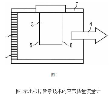
May 22, 2023