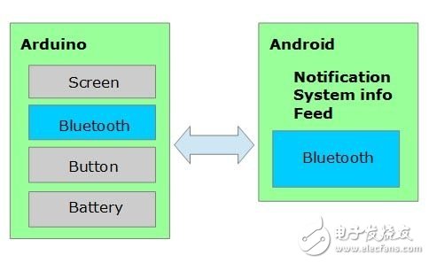
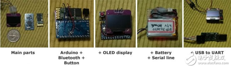
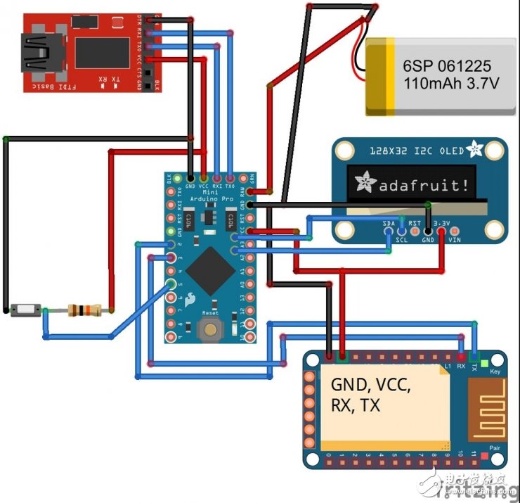
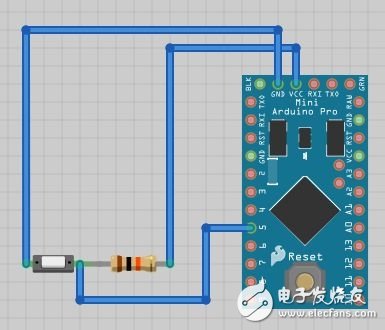
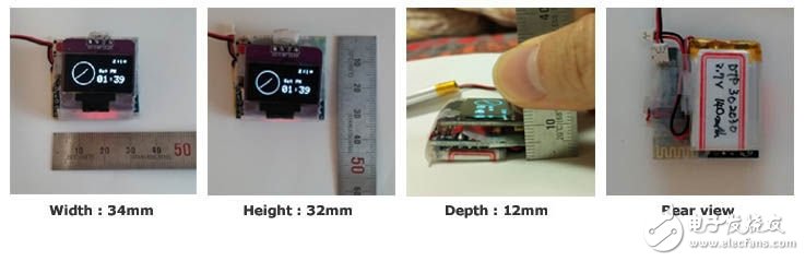
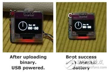
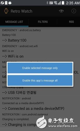
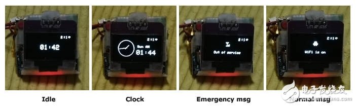
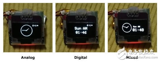
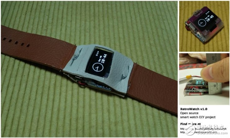
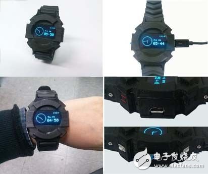
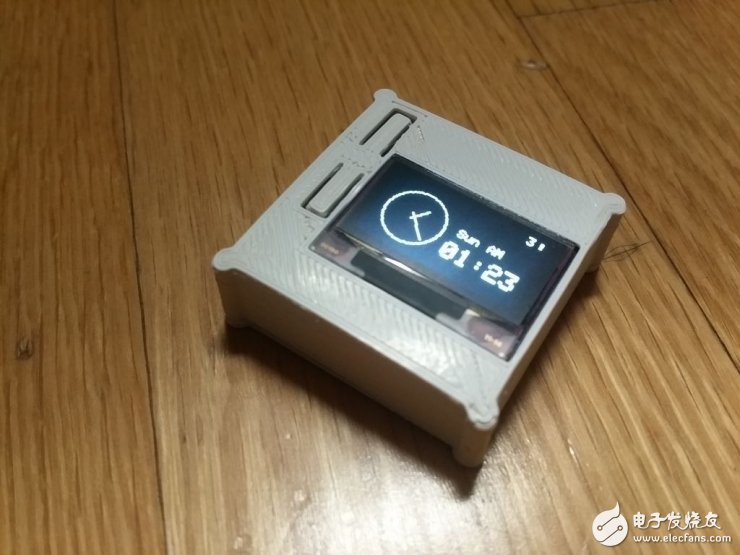
When it comes to wearable devices, we generally think of smart watches first. It is certainly good to buy a stylish smartwatch, but as a maker, you can also choose to make one yourself like me! I named this DIY smart watch RetroWatch. The entire project is based on Android and Arduino development boards. All software and hardware designs of the project are open source. You can download the source code on GitHub or contribute your own strength. It is also worth mentioning that RetroWatch already supports u8glib, which allows you to choose any screen you want to use (including OLED), and the RAM occupied by the screen can also become less. The first step: system structure design As shown in the figure above, the structure of RetroWatch is relatively simple: the hardware platform is based on Arduino, and there is only one control button on it. In addition, I also developed an Android-based application that allows the watch to connect to Android devices via Bluetooth, so that we can view RSS pushes and system notifications on Android devices through RetroWatch. Step 2: Component preparation Because what we are going to do is a smart watch, ensuring the compactness of each component is also one of the keys. Arduino microcontroller I chose the smallest Arduino, ProMini, which is a lightweight version of UnoR3. There is no USB interface chip on it, so an additional USB to UART module is needed. This Arduino has two versions (3.3v/5v) with different working voltages. I chose the 3.3V version because both the Bluetooth module and the display support 3.3V, and 3.7V LiPo batteries can also be used normally. The operating frequency of the 3.3V version of Arduino is 8MHz, and the operating frequency of the 5V version is 16MHz, but 8MHz is sufficient. Generally, the core processing device of ArduinoProMini is ATmega328 single-chip microcomputer, its RAM is 2KB; and the Arduino version of ATmega128 with only 1KBRAM is not enough. Bluetooth HC~06 Bluetooth module is more common. One of them has an interface board with a reset button and an LED, but the volume is relatively large. In view of the fact that the interface board is of little significance to this project, it also increases the cost, so the HC~06 without the interface board is selected here. Display screen We need a display that is small enough and consumes low power. I finally chose the 0.96-inch 128&TImes;64 OLED display from Adafruit, which supports I2C, SPI, and can be easily connected to Arduino. I chose I2C and SSD1306 driver chip here. battery My choice is a 3.7V LiPo battery with a capacity of 140mAh. General use can last for 7 hours. Likewise, choosing the size of the battery is important. other In addition to wires and other components, a 10kΩ resistor (used for button connection) is also needed. Step 3: Assembly The hardware structure connection diagram of the whole system is as follows: Bluetooth connection to Arduino: VCC~3.3V GND~GND TX~D2 RX~D3 Connect OLED to Arduino: GND~GND VCC~VCC SDA~A4 (analog pin 4) SCL~A5 (analog pin 5) If you are using the SPI interface, you can refer to the Adafruit tutorial to connect as follows: D1: MOSI~ArduinoD11 (MOSI) D2:MISO~ArduinoD12 (MISO) (optional) D0: CLK~ArduinoD13 (SCK) DC: DC (data command) ~ ArduinoD8 (or other) CS: CS (chip selection) ~ ArduinoD10 (SS) RES:RESET~ArduinoD9 (or other) Button: The connection method is shown in the figure. Note that a 10kΩ resistor is used here. Connect the battery to the Arduino: Positive~RAW Negative~GND Connect USB to UART module to Arduino: 3.3V~VCC TXD~RXD RXD~TXD GND~GND The installation dimensions are as follows: Step 4: Compile and upload the Arduino code The completed Arduino project can be downloaded on GitHub. After downloading, don't rush to compile, you also need to configure the development environment first. Install graphics driver: First, you need to install the graphics processing library Adafruit_SSD1306 and Adafruit-GFX-Library, so that images can be displayed on the OLED. (In some development environments, the Adafruit library will conflict with the Robot_xxx library; if this happens, back up the Robot_xxx library and delete it from the library folder.) Warning: If you are using an OLED with SH1106 driver, then download the Adafruit_SH1106 driver on GitHub. In addition, this project also supports u8glib. You can download the version that supports Arduino from its official homepage. Copy the bitmap image header file: Copy the bitmap.h file in the RetroWatchArduino folder to the path/Arduino installation folder/Arduino/hardware/libraries/RetroWatch. If there is no such path, you can create it yourself. Modify the source code: Open ArduinoIDE and load RetroWtchArduino.ino. If the pins you use are different from this tutorial, you need to modify the pin definitions: SoftwareSerialBTSerial(9, 8);//Bluetooth TX, RX connection pins intbuttonPin=5;//Button pin display.begin(SSD1306_SWITCHCAPVCC, 0x3C);//OLEDI2C address, replace Ox3D with your address If you are using u8glib, then load the RetroWatchArduino_u8glib.ino file, and then pay attention to the following code: U8GLIB_SSD1306_128X64u8g (U8G_I2C_OPT_NONE|U8G_I2C_OPT_DEV_0);//Modify according to the display screen you choose SoftwareSerialBTSerial(2,3);//Bluetooth TX, RX connection pins intbuttonPin=5;//Button pin If you are using Adafruit's graphics library and use the Reset pin of OLED, then connect the Reset of OLED to the D8 pin of Arduino. Of course, you can also customize: #defineOLED_RESET8 Adafruit_SSD1306display (OLED_RESET); Compile and upload: After the above steps are completed, compile and upload, after success, RetroWatchArduinoLogo and AdafruitLogo will be displayed on the display. The screen will display 00:00 after Logo, as shown in the following figure: Step 5: Android software and its source code Because the version after Android4.3 only supports reading notification information from the app, please make sure that your Android device is installed with Android4.3 or a newer system version. But if you are using a version lower than 4.3, you can use another castrated version of the application: you can receive notifications through your smart watch, but you cannot read the content. The application source code can be viewed on GitHub, or can be installed directly through GooglePlayStore (RetroWatch or RetroWatchLE for low-version systems). After the Android software is installed, check whether the system has granted it permission to read notifications. Next, turn on the Bluetooth of the mobile phone and pair the Bluetooth of the Android phone with the Arduino. Then select the connected Arduino in the RetroWatch software, and "Connected" is displayed on the interface, which means the connection is successful. Click the menu, select DatatransfertoWatch (transfer data to watch), and then the device will use Bluetooth to transfer time and information to the smart watch. Because the performance of watch hardware is limited, we need to realize many functions through Android applications. The main function of the watch itself is display. In the Android app, you can set the types of pushable messages (only English characters are supported) and status notifications (mobile phone battery power and signal strength, etc.), and you can also push the RSS subscribed in the app (you can subscribe to the weather RSS to use The weather is displayed on the watch). Updates are synchronized every 30 minutes. In addition, 65 different display icons are provided in the application, and you can define the settings yourself. Step 6: Watch function introduction Once installed, it’s time to explore our smartwatch. The smart watch system works in the following mode: Startup display: display the Logo and the watch starts. Clock display: Display the time on the connected Android phone. In addition, the time display can also be modified. Currently, three modes of analog display, digital display and mixed display are provided. If you click the button once, the watch enters the emergency information display mode. If there is no data update or operation within 10 minutes, the display interface will switch to the standby interface. Emergency information display: When the user clicks the button or has a new emergency information input, the watch enters this mode. The user can click the button again to view the next message, and the watch will automatically display the next message if it is not operated for 10 seconds. After the information display is complete, the watch switches to the normal information display. Because RAM is only 2KB, very small. Therefore, the smart watch stores up to 3 urgent messages, and when there are more than 3, the oldest messages are automatically deleted. Normal information display: After the emergency information is displayed, the watch will continue to display the normal information, and the next information will be displayed when you click the button or do not operate for 5 seconds. After the information display is complete, the watch switches back to the clock display. Up to 7 general information can be stored. Standby display: If there is no data update or operation within 10 minutes, the display interface will switch to the standby interface. In this mode, the watch interface only displays the indicator (selectable in the Android application) and the time of hh:mm mode, and its power consumption is also reduced. In the standby mode, click the button or receive a new message, the watch enters the clock display mode. The following is a demonstration video of the working process: Step 7: Making the external structure You can make a simple package yourself: You can also download the 3D file to make a cool watch: Of course, you can choose not to wear a watch, and it is also good to be a desktop reminder:
Goldshell Miner:Goldshell Mini-DOGE Pro,Goldshell LT Lite,Goldshell X5,Goldshell LT5,Goldshell LT5 Pro,Goldshell LT6,Goldshell Mini-DOGE
Goldshell Miner is an industry-leading technology company. The company was founded in 2017, we are focusing on high-performance miners and application fields. In the past few years, Goldshell Miner has successfully completed the R&D, mass production, and sales of multiple miners in LTC, CKB, HNS, Sia and other cryptocurrencies. The headquartered is based in Shanghai, Goldshell Miner has offices in Hangzhou, Hong Kong, Singapore,etc. The current R&D personnel account for more than 70% of the company. The core team has more than 10 years of experience in the integrated circuit field. Aiming to become an excellent blockchain computing power provider, and promoting the development of the industry, Goldshell has established an efficient operation system from algorithm research, batch production and delivery, which based on a strong core team and excellent system capabilities. Goldshell continuously improved the computing performance and competitiveness of products, to provide high-performance and high-reliable computing infrastructure and services for the development of digital economy. Especially our household miner-BOX series, allow more customers to join in the market since our product are small, quiet, affordable, and friendly to beginners so that everyone could start mining at home.
goldshell mining machine,goldshell ltc miner,goldshel lt5,goldshell mini doge pro,goldshell lt6 Shenzhen YLHM Technology Co., Ltd. , https://www.asicminer-ylhm.com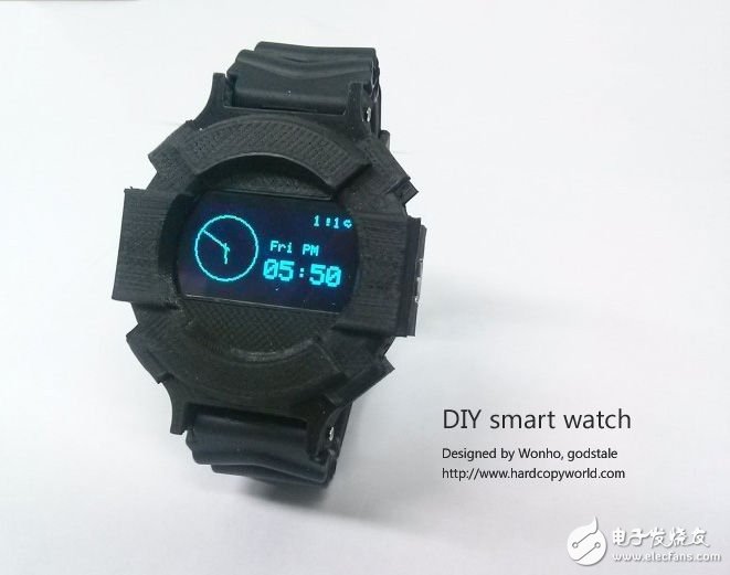
May 03, 2023