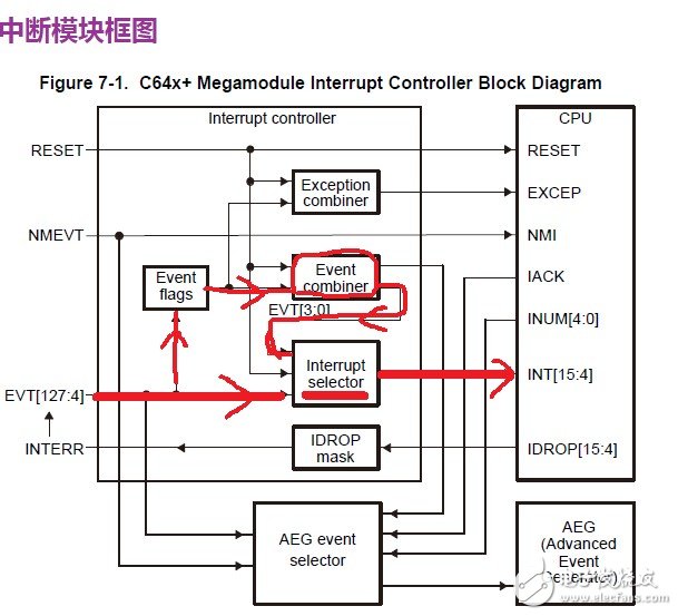
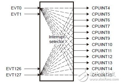
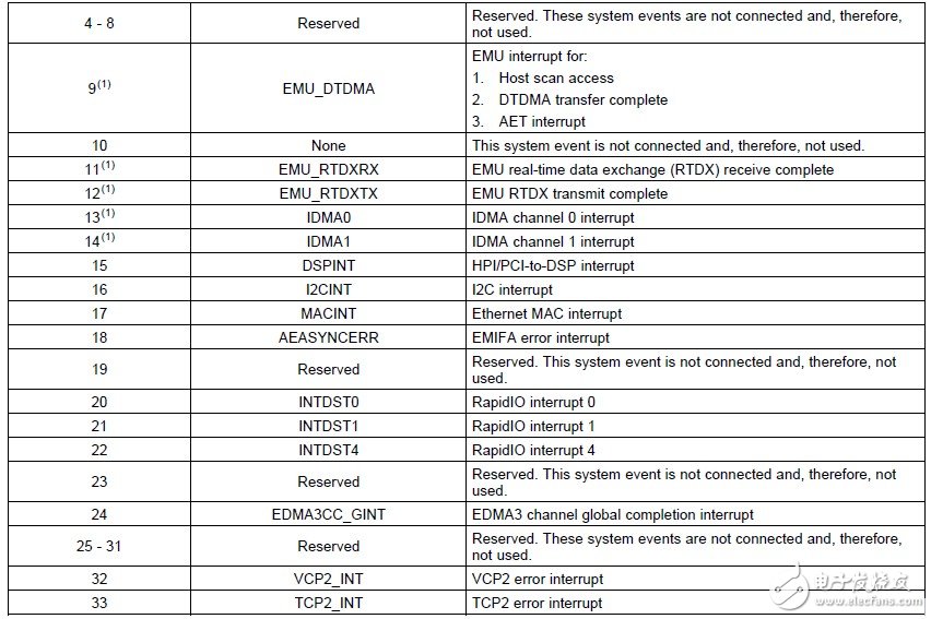
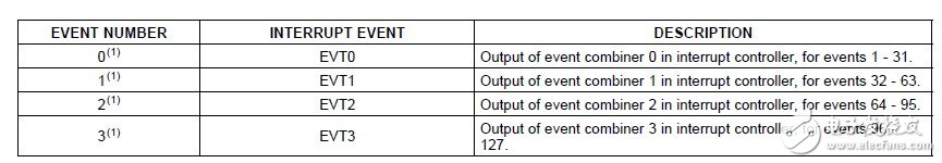
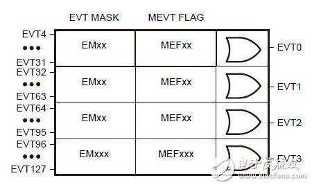
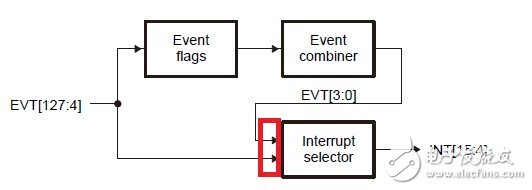
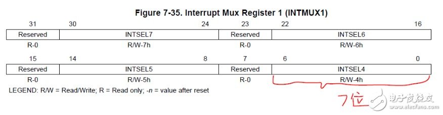
This article is mainly about the relevant introduction of TMS320C6455, and focuses on the use of the interrupt system of the TMS320C6455 series DSP has been elaborated in detail. TMS320C6455 is a new high-performance single-core fixed-point DSP launched by TI. It is a new product developed by TI based on the third-generation advanced VeloviTI VLIW (ultra-long instruction word) structure. It can do a lot in communications, medical images, and wireless transmission. The main frequency of TMS320C6455 has reached 1GHz, and the instruction cycle is 1ns. 8 32-bit instructions are executed every cycle, and the maximum peak speed reaches 8000MIPS. this means. Under 1G clock frequency, 8000 16-bit "16-bit MACs can occur in 1 second. TMS320C6455 also has a Seria/RapidlOfr) bus, the interconnection rate is as high as 25Gbits per second, which achieves extremely high multi-processing performance and reduces The system consumption is 12 times faster than the previous external memory interface, which makes the multi-DSP cascade connection very convenient. The TMS320CC6455 chip is based on the L1/L2 memory structure of the C64xx core. There is a large amount of storage space integrated on the chip. L1P is 32K Bytes, L1D is 32K bytes and L2 is 2M bytes, which is double the memory capacity of the previous C64x device, and both L1P and L2 can be directly mapped to the storage space. The peripheral bus of TMS320C6455 includes: an internal integrated circuit bus (I2C). Two multi-channel buffer serial bus fMcBSPs), two 64-bit general-purpose timers (can be configured as four 32-bit timers), a configurable 16-bit or 32-bit host interface (HPI6/HPI32). A PCI bus, a 16-pin general-purpose input/output port (GPIO), and a 10/100/1000M Ethernet media access controller (EMAC). A seamless external memory interface (64-bit EMIFA), a 32-bit DDR2 SDRAM interface. Because C6455 comes with Gigabit EMAC, a Gigabit Ethernet port can be realized by connecting the PHY physical layer chip. The realization of Gigabit Ethernet makes the data transmission between C6455 embedded processors and desktop computers extremely convenient. TI provides NDK (Network Develop Kit) for processors such as C6455. The use of NDK can simplify the implementation of data transmission protocols such as TCP/IP or UDP in C6455. Carefully observe the above picture, you can see that C6455 has the following types of interrupts: 1. Reset 2. NMI non-maskable interrupt 3. EXCEP hardware exception 4. 12 ordinary interrupts INT [15:4] The one we use the most is the ordinary interrupt, so this is also the focus of this article. Next, step back along INT [15:4] and see the Interrupt Selector, which functions like a shuffle, which selectively maps all interrupt events. As shown below: Looking at this picture, it is not difficult for us to find that the interrupt selector is a 128-》12 mapping, which means that 116 system events have been filtered out. Then go back and you can see that the interrupt selector has three inputs, namely: RESET Event [3:0] Event [127:4] The RESET is ignored and the hardware restarts. EVENT [127:4] is a system event. The number of this event varies depending on the chip. Take 6455 as an example, part of the mapping situation is shown in the following two pictures: It is not difficult to see that these numbers are fixed and basically cover the events of all modules on the chip. Finally, the more special event is Event[3:0], which is a combined event, which should be clear at a glance through the introduction in the figure below. It can be seen that Event0 corresponds to the combined event of events 4-31, Event2 corresponds to the combined event of events 32-63, and so on. So, how to combine? This has to start with the register. First, let's look at the following three register groups: (Note: Each group is 4 32-bit registers, EVTxxx0 [3:0] of each group is not used, so there is no combination event involved here) When a system event occurs (124), their corresponding bits in the event flag register (EVTFLAGx) will be set to 1. At this time, the interrupt flag can be cleared by writing 1 to the corresponding bit in the EVTCLR register, and then the interrupt service routine is executed. If it is not cleared, problems will arise when the same event occurs again. Therefore, it is necessary to manually clear the interrupt flag! And it can only be cleared by writing 1 to the EVTCLR register, not directly writing 0 to the EVTFLAG register, because the EVTFLAG register is Read Only. In addition, the significance of the EVTSET register is that we can manually generate an interrupt, which allows us to test the function of the interrupt service routine. After introducing the three basic register sets above, we can begin to discuss the mechanism of combined events. First look at the picture below: It can be clearly seen that the 124 events are divided into 4 groups. Then after the operation of the two registers, a combined event is generated. The following describes the two register groups EVTMASK and MEVT FLAG. The EVT MASK register group is used to determine which events in each group are masked. By default, no events are blocked (all 0s). In view of the fact that the eventual mechanism of the final combined event EVTx is to perform an OR operation on all events in the Group, that is, as long as one event occurs in the Group, it represents the occurrence of a combined event. for example: If EVTMASK3=0x0FFFFFFF, it means that only events 124, 125, 126, and 127 participate in the combination. Other events 96-123 were ignored. The MEVT FLAG register has the same value as the EVT FLAG register, indicating whether an event has occurred. In this way, once the values ​​of the EVTMASK and MEVT FLAG registers are known, it can be determined whether the combined event EVTx (0<=x<=3) has occurred. Through the above introduction, the interrupt mechanism of C6455 should have been very clear, and then post a picture to consolidate the content mentioned above: Having said that, we have a very clear understanding of the red box in the above picture and the things before it. The following is the mechanism of Interrupt Selector. In fact, it is very simple. Configure the corresponding event numbers for each of the 12 interrupts. Only 3 registers are required. They are INTMUX1, INTMUX2, and INTMUX3. Posting a picture should be very clear. for example: Suppose I want to map INT4 to GPIO4, then by looking up the previous figure, I found that the event number of GPINT4 is 55, then just set the lower 7 bits of INTMUX1 to 0x37. In addition, the official document also said the following paragraph: It can be seen that INT4 has the highest priority and INT15 has the lowest priority This is the end of the related introduction about TMS320C6455. I hope this article will give you a more comprehensive understanding of TMS320C6455. Related reading recommendations: High-speed SRIO interface design based on TMS320C6455 Related reading recommendations: Optimized design of Viterbi decoding program based on TMS320C6000 series DSP Led Floor Panels,Led Dance Floor Panel,48W Led Light Panel,Floor White Uplight Panel Led Kindwin Technology (H.K.) Limited , https://www.ktlleds.com

May 25, 2023