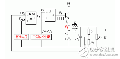
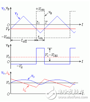
The process of regulating the output voltage by the regulation of the circuit is called voltage regulation. A circuit that maintains a constant output voltage when the input voltage, load, ambient temperature, and circuit parameters change. This circuit provides a stable DC power supply and is widely used in a variety of electronic devices. Adjustment component, reference voltage circuit, sampling circuit, comparison amplification circuit There are many classification methods for regulated power supply classification and regulated power supply. According to the type of output power supply, there are DC regulated power supply and AC regulated power supply. The connection mode between the voltage regulator circuit and the load is divided into a series regulated power supply and a parallel regulated power supply; according to the working state of the adjusting tube, there are a linear regulated power supply and a switching regulated power supply; according to the circuit type, there are a simple regulated power supply and a feedback type. Regulated power supply, and so on. Such a wide variety of classifications often make beginners puzzled and don't know where to start. In fact, it should be said that there are certain hierarchical relationships between these seemingly numerous classification methods. As long as the level is clarified, it is natural to distinguish the types of power sources. The principle of the switched regulator power supply can be illustrated by the circuit of Figure 1. It consists of an adjustment tube, a filter circuit, a comparator, a triangular wave generator, a comparison amplifier, and a reference source. Figure 1 Schematic diagram of switching regulator power supply The triangular wave generator generates a square wave vB through the comparator to control the on and off of the adjustment tube. When the adjustment tube is turned on, charge the inductor. When the regulator is turned off, a bleed path must be provided to the current in the inductor. The freewheeling diode D can do this to help protect the adjustment tube. According to the wiring of the circuit diagram, when the amplitude of the triangular wave is smaller than the output of the comparison amplifier, the comparator outputs a high level. (The portion of the output waveform whose potential level is higher than the minimum value of the high level, and the square wave, the portion where the square wave exists. ). The on-time of the corresponding adjustment tube is ton; otherwise, it is low level (the part of the output waveform whose potential level is lower than the low level maximum, and the square wave is equivalent to the part where the square wave does not exist). The cut-off time of the corresponding adjustment tube is toff. In order to stabilize the output voltage, feedback should be introduced in the form of voltage negative feedback to determine the connection between the reference source and the comparison amplifier. Let the output voltage increase, FVO increases, the output amplifier VF of the comparison amplifier decreases, the comparator square wave output toff increases, the conduction tube conduction time decreases, and the output voltage decreases. Played a role in voltage regulation. The waveform of each point is shown in Figure 2. Since the emitter output of the adjustment tube is a square wave, there is a filter inductor, so that the output current iL is a sawtooth wave and tends to be smooth. The output is a rippled DC voltage. Ignoring the DC resistance of the inductor, the output voltage VO is the average component of vE. Then there is q is called the duty cycle, and the square wave high time is a percentage of the entire cycle. When the input voltage is constant, the output voltage is proportional to the duty cycle, and the output voltage value can be controlled by changing the width (duty ratio) of the square wave of the comparator output. This type of control is called pulse width modulation (PWM). Figure 2 Switching power supply waveform From the above analysis, the following conclusions can be drawn: 1. When the adjustment tube works in the switch state, the power consumption is greatly reduced, and the power supply efficiency is greatly improved; 2. The adjusting tube operates in the switching state, and in order to obtain the DC output, a filter must be added at the output end; 3. The output voltage value can be easily changed by the pulse width control; 4. Power transformers can be omitted in many situations; 5. Due to the higher switching frequency, the volume of the filter capacitor and the filter inductor can be greatly reduced. docking station for macbook air,docking station for laptop,docking station usb c,USB C HUB,thunderbolt 3 usb type c hub Shenzhen Konchang Electronic Technology Co.,Ltd , https://www.konchang.com

How Circuit Regulators Work
September 14, 2022