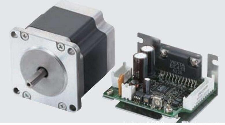
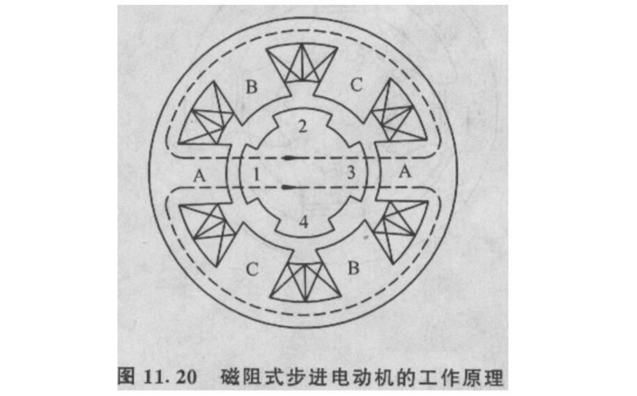
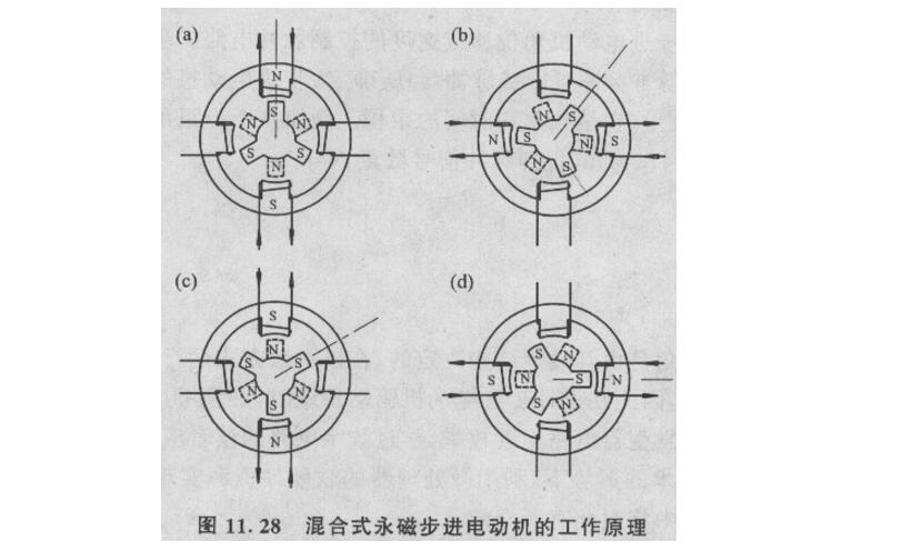
A stepping motor is a discrete value control motor that converts an electric pulse excitation signal into a corresponding angular displacement or linear displacement. This electric motor moves one step each time an electric pulse is input, and is also called a pulse motor. Stepper motor drive power from the variable frequency pulse signal source, pulse distributor and pulse amplifier, which drives the power supply to the motor winding pulse current. The performance of the stepper motor depends on the good cooperation between the motor and the drive power supply. Stepper motors have the advantages of no accumulation of errors, simple structure, easy use and maintenance, low manufacturing cost, and large stepper motor capacity to drive load inertia. They are suitable for small and medium-sized machine tools and places where speed accuracy is not high. The disadvantages are low efficiency. , Hot, sometimes "out of step." Electromechanical stepper motors consist of iron cores, coils, and gear mechanisms. When the solenoid coil is energized, magnetic force will be generated to push the iron core to move, the output shaft will be rotated by the gear mechanism at an angle, and the output shaft will be kept in a new working position by the anti-rotation gear; the coil will be energized and the shaft will be rotated by another angle. Stepping motion is performed in order. The magnetoelectric stepping motor has a simple structure, high reliability, low price, and wide application. There are permanent magnet type, magnetoresistive type and hybrid type. (1) Permanent magnet stepping motor. The rotor has permanent magnet poles that generate alternating polarity magnetic fields in the air gap and the stator is composed of four-phase windings (see figure). When the A-phase winding is energized, the rotor will turn to the direction of the magnetic field determined by the phase winding. When the A-phase power is off and the B-phase winding is energized, a new magnetic field direction is generated. At this time, the rotor is rotated by an angle and is positioned in the direction of the new magnetic field. The order of the excited phases determines the direction of rotation of the rotor. If the stator excitation changes too quickly, the rotor will not be able to keep up with the change of the stator magnetic field direction and the rotor will be out of step. The low starting frequency and operating frequency is a disadvantage of the permanent magnet stepping motor. However, permanent magnet stepping motors consume less power and have higher efficiency. In the early 1980s, a disk-type, permanent disk-type stepping motor was used as the rotor, so that the step angle and the operating frequency reached the level of the reluctance stepping motor. (2) Magnetoresistive stepping motor. The inner and outer surfaces of the stator core and the rotor core are provided with adjacent tooth slots that are distributed according to a certain rule, and the magnetic resistance of the magnetic circuit changes due to changes in the relative positions of the tooth slots of stator and rotor cores, thereby generating torque. The rotor core is made of silicon steel or soft magnetic material. When a certain phase of the stator is excited, the rotor will turn to the position where the magnetic resistance of the magnetic circuit is minimized. When the other phase is excited and the rotor is turned to another position to minimize the reluctance of the magnetic circuit, the motor stops rotating. At this time, the rotor rotates through a step angle θb, where N is the number of revolutions the rotor rotates through a pitch; ZR is the number of rotor teeth. Magnetoresistive stepper motors have many structural forms. The stator core has a single-stage type and a multi-stage type; the magnetic circuit has a radial direction and an axial direction; the number of winding phases is three-phase, four-phase, and five-phase. Reluctance stepping motor step angle can be achieved 1 ° ~ 15 °, or even smaller, the accuracy is easy to ensure, start and run frequency is higher, but the power consumption is greater, less efficient. (3) Hybrid stepping motor. Its stator and rotor core structure is similar to the reluctance stepping motor. The permanent magnets of the rotor generate a unipolar magnetic field in the air gap, which is also modulated by the slots of the soft magnetic material on the rotor. The hybrid stepping motor combines the advantages of both the permanent magnet stepper motor and the reluctance stepper motor. The motor has a small step angle, high precision, high operating frequency, low power consumption, and high efficiency. There are two types of reaction and Sawyer. Sawyer linear stepping motor consists of a stationary part (called reaction plate) and a moving part (called a mover). The reaction plate is made of a soft magnetic material and has teeth and grooves evenly spaced on it. The motor's mover consists of a permanent magnet and two magnetic poles A and B with coils. The mover is supported by the air cushion to eliminate the mechanical friction during the movement, so that the motor runs smoothly and improves the positioning accuracy. The motor's maximum speed of up to 1.5 meters / second, acceleration up to 2g, positioning accuracy of up to 20 microns. Two Sawyer type linear stepping motors are vertically assembled with each other to constitute a planar motor. By using different combinations of control currents for the two motors in the x-direction and y-direction (Figure 3), the motor can be moved in the plane with any geometrical path. A large-scale automatic plotter is a new type of device that combines a computer and a planar motor. Planar motors can also be used in laser cutting systems with control accuracy and resolution of up to several tens of micrometers. We use Figure 11.20 to illustrate how this type of motor works. The stator of the reluctance stepping motor is equipped with a multi-phase excitation winding, and Fig. 11.20 is a schematic diagram of the most commonly used three-phase winding stepping motor. Three-phase windings form six magnetic poles. The rotor is made of soft magnetic material and has 4 teeth on it. When the A-phase winding is energized and the B- and C-phase windings are not energized, the reluctance torque causes the axes of the teeth 1 and 3 and the stator A due to the magnetic flux drawing the minimum path of the reluctance and minimizing the reluctance of the magnetic circuit. Phase pole alignment. Energizing the B phase at the next moment, disconnecting the A phase power supply will align the axes of the rotor teeth 2, 4 with the B phase magnetic poles and the rotor will therefore rotate anticlockwise by 30° as a whole. Therefore, circulating the three winding wheels in the order of ABC-A... will cause the rotor to rotate continuously in the counterclockwise direction. If energized in the order of ACBA..., the rotor will rotate clockwise. From this we can get the following judgments: (1) The direction of rotation of the stepper motor depends on the order in which the windings are energized; (2) The rotational speed of the motor depends on the frequency of the windings being turned on and off; (3) Each time the winding is energized, the distance between the stepping angles of the rotors is l/m, which is the angular distance between the rotor teeth. That is, the step angle is l/m of the pitch. The stepping angle of each step in the above stepping motor model is 30°, and it is difficult to meet the requirements of fine control. The actual motor adopts the structure shown in Figure 11.21. In this kind of structure, the poles of the stator poles are opened with some evenly distributed small teeth, and the surface of the rotor is evenly distributed with small teeth. The angular distance measured between the rotor teeth and the pitch of the stator are exactly equal. The so-called pitch is the angle between the adjacent two tooth centerlines, also known as the pitch angle DT = 360 ° / Zr type DT- pitch; Zr-rotor teeth. Since these small teeth are opened, the rotation of the rotor when the winding is switched can find a position with the smallest reluctance within the range of DT. This greatly reduces the step angle and improves the resolution of the movement. From the analysis of Fig. 11.20, it is noted that when the teeth of the rotor and the teeth of a certain magnetic pole completely match, for the m-phase motor, the teeth of the rotor and the other two-phase magnetic poles must be staggered by the l/m pitch. For a three-phase motor, when the A-phase is energized, the small teeth of the rotor and the small teeth on the magnetic poles of the B and C phases must be staggered by DT/3 in sequence. Under this constraint, the number of teeth of the rotor cannot be any value, but must satisfy the following conditions: Zr/2p=K±1/m, ie, Zr=2p(K±1/m)=2pK±2 Where K-positive integer; p-pole pair number; m-phase number, p=m. The motor stator in the figure has four teeth that are evenly distributed along the circumference. The coils are wound on the teeth and connected in pairs. Two rotors with different polarities each have 3 teeth. In the figure, the S-segment is indicated by a solid line, and the N-segment is indicated by a dashed line. The two rotors are alternated by a half pitch. When there is no current in the winding, because the permanent magnets in the rotor always try to reduce the reluctance in the magnetic circuit, the rotor will tend to a limited number of positions until each of the N pole and S pole rotor has one tooth aligned with the stator pole. For the motor in the figure, there are 12 such positions. The torque holding the rotor at these positions is usually not large, which is called the holding torque. If there is a current through a phase winding as shown in Fig. 11.28(a), the N and S poles generated on the stator will attract the teeth on the opposite rotor segment. In this case, only the same number of teeth as the rotor. In a stable position, the torque pulling the rotor from the positioning position is much larger, which is called locking torque. The way of energization is switched from Figure (a) to Figure (b), and the stator magnetic field is turned 90. , and will attract another pair of teeth, the result of the rotor rotation 30. Is equivalent to a whole step. In the diagram (b) to (c), the excitation returns to the previous winding, but the direction of the current is reversed, allowing the rotor to advance one more step. In Figure (d), reversing the current of the second phase winding can be further advanced. In this way the rotor passes a pitch. From step (d) to step (a), this is repeated so that the motor's rotational motion is formed, requiring 12 steps per revolution. Obviously, by energizing the stator windings in the reverse order, the motor will reverse. Usually the small teeth of the stator are evenly distributed with a different pitch than the rotor. In a motor with a large number of teeth (see Figure 11.27), the pitch arrangement of the stator and the rotor is such that only the two teeth opposite the rotor are 180 apart. . The stator teeth are perfectly aligned. At the same time, the distance is 90. The stator teeth at the mechanical corners are completely staggered. For such a hybrid motor, the following formula can be used to calculate the number of steps per revolution N=┃NrNs/(Ns-Nr)┃ Among them, N is the number of steps per revolution; Nr and Ns are the number of teeth of the rotor and the stator, respectively. For the example in Figure 11.27, where Nr and Ns are 8 and 10, respectively, the motor can be calculated for 40 steps per revolution with a step angle of 9. The stepping motor is designed for precise displacement. In order to achieve high accuracy, the efficiency must be low and the current is large. It is not possible to operate the DC motor when it is powered on. The stepper motor is controlled by a single chip pulse to control the torque, the microcontroller drive current is small, can not drive the motor windings, to use the drive circuit to generate a larger current, direct drive will burn the microcontroller.
A new rule from the Drug Enforcement Administration (DEA) threatens to upend the American hemp industry, and could even result in criminal prosecutions for manufacturers of CBD and delta-8 THC products.
The DEA says the [interim final rule," issued Aug. 20, is simply a matter of adjusting its own regulations to account for changes to the Controlled Substances Act that were mandated by the 2018 Farm Bill (or Agricultural Improvement Act) that legalized hemp and CBD production. The new rule [merely conforms DEA`s regulations to the statutory amendments to the CSA that have already taken effect," says the agency. The new rule doesn`t break any ground, according to the DEA.
But many experts on cannabis and hemp law say the DEA rule creates a potential pathway the law enforcement agency could use to prosecute hemp processors and producers of CBD (cannabidiol) and delta-8 THC (or Δ8THC) products. There are two issues: partially processed CBD, and [synthetically derived" delta-8 THC.
Cbd Pod System Oem,Cbd Vape Pod Oem,Best Cbd Pod System,Cbd Pod System Shenzhen MASON VAP Technology Co., Ltd. , https://www.e-cigarettefactory.com


Stepper Motor Overview
April 15, 2024