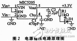
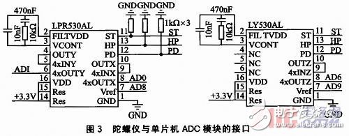
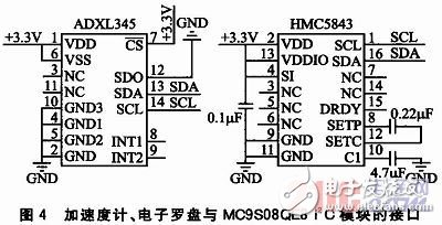
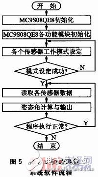
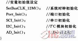
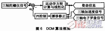
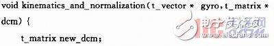
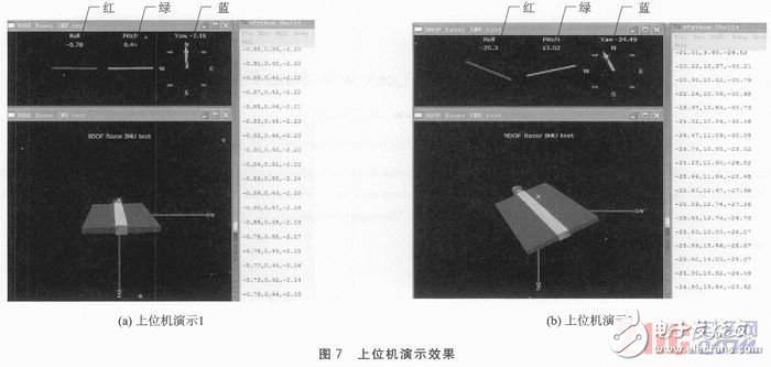
Traditional attitude measurement uses high-precision gyroscopes and accelerometers and other attitude sensors, which are bulky and expensive. Because of its small size, low price, and low power consumption, MEMS products are currently known as a major reform of the traditional inertial measurement combination, and are increasingly used in attitude measurement applications. Moreover, with the rapid development of MEMS technology and its penetration into various disciplines, its various aspects of performance, such as accuracy, robustness, and dynamic response, have been greatly improved. With the continuous development of embedded technology, application-centric embedded systems have penetrated into all aspects of our daily lives due to their small size, low power consumption, high reliability, good scalability, and high integration of software and hardware. It has been applied in all walks of life. The combination of embedded and MEMS enables the attitude measurement system to meet the needs of low-cost, low-power, and miniaturized applications, and has brought tremendous progress to the consumer electronics field, such as the gravity sensor and compass in smart phones, as well as aviation, Industry, automotive, medical, environmental monitoring, communications and other fields have brought very broad application prospects. This article uses three-axis MEMS gyroscope, three-axis MEMS accelerometer, three-axis MEMS electronic compass and Freescale microcontroller MC9S08QE8 to form an embedded attitude measurement system. Due to its good dynamic performance, the gyroscope is used to obtain real-time attitude information. However, because the gyroscope will have an offset, and the accelerometer and electronic compass have superior static performance, they are used to correct the error in the gyroscope attitude calculation process. This system is mainly composed of single-axis gyroscope LY530AL, dual-axis gyroscope LPR530AL, three-axis MEMS accelerometer ADXL345, three-axis MEMS electronic compass HMC5843 and microcontroller MC9S08QE8. Among them, the dual-axis gyroscope in the X and Y directions and the single-axis gyroscope in the Z-axis direction are combined into a three-axis gyroscope. Their signals are collected by the ADC module of the microcontroller MC9S08QE8, and the acceleration signals and electronic compass signals are transmitted through the I2C bus. To the microcontroller. These 9 signals are first processed in the single-chip microcomputer, and then the posture calculation algorithm program in the single-chip microcomputer obtains 3 attitude angle information. These 3 information are transmitted to the upper computer through the serial port module of the single-chip microcomputer MC9S08QE8 for demonstration, embedded attitude measurement The system structure block diagram is shown as in Fig. 1. 1.1 Three-axis MEMS gyroscope The three-axis MEMS gyroscope in the system is a combination of ST's single-axis Z-direction gyroscope LY530AL and dual-axis X, Y-direction gyroscope LPR530AL. They adopt the principle of capacitive micro-mechanical gyroscope. Because ST Company has chosen the tuning fork method, and the vibration drive circuit adopts a double closed-loop control structure, the stability and resolution of the gyroscope are significantly improved. The measuring range is up to ±300°/s, with a self-test function, the output is integrated with a low-pass filter circuit, the working voltage is 1.8-3.6 V, and the standby mode current is less than 1μA. 1.2 Three-axis MEMS accelerometer The three-axis MEMS accelerometer in the system selects ADXL345 of ADI Company. ADXL345 is a three-axis, digital output acceleration sensor based on iMEMS technology, with variable measurement ranges of ±2g, ±4g, ±8g, and ±16g. The 32-level FIFO storage in the chip can buffer data, thereby reducing the burden on the processor and reducing system power consumption. ADXL345 has high resolution and sensitivity, 3 mm × 5 mm × 1 mm ultra-small package, 40-145μA ultra-low power consumption and standard I2C or SPI digital interface, very suitable for mobile device applications. 1.3 Three-axis MEMS electronic compass The three-axis MEMS electronic compass in the system uses Honeywell's HMC5843, which uses Honeywell's anisotropic magnetoresistance (AMR) technology, and consists of Honeywell's high-precision HMC11 8X series magnetoresistive sensors , It has high sensitivity and reliability in low-intensity magnetic field sensors. 2. 16-3.3 V low-voltage power supply, 0.66 mA current consumption, and a small volume of 3 mm × 3 mm × 0.9 mm, has obvious advantages in consumer electronic equipment, navigation systems. 1. 4 MCU MC9S08QE8 The one-chip computer in the system adopts MC9S08QE8 of Freescale Company. MC9S08QE8 uses many new technologies, such as battery life, extended technology, enhanced low-power performance, and advanced operating capabilities under ultra-low voltage. At the same time, it has a very high level of integration and integrates many system-level functions, such as 12-bit high-precision A/D converters, timers, SPI, I2C, SCI and other common modules, which are very suitable for low-power, low-cost applications. 2.1 Power supply module The power supply voltage regulator circuit of this system supplies power for all the equipment of the whole system. Taking into account the digital and analog sensors involved in the system, it uses a linear voltage regulator chip MIC5205 with low noise, low drift and a supply voltage of 3.3 V. The schematic diagram of the power supply voltage regulator circuit is shown in Figure 2. Among them, C1 is the capacitor connecting the internal voltage reference source of the chip and GND to reduce the noise of the output voltage, and C2 is the capacitor between the output and GND to prevent the circuit from oscillating. The capacitance of C2 is related to C1, but when C1 is 470 nF, C2 is generally 2.2 μF. D1 is the indicator light of the power supply. 2.2 Gyroscope and ADC module The ADC module inside the MC9S08QE8 microcontroller is based on a successive approximation 12-bit analog-to-digital converter. It provides 10 input channels, can be configured to use time conversion speed and power consumption, and can be set to compare presets to ensure that some data that does not meet the requirements need not be saved. Among them, the most high-performance feature is that you can set the continuous sequence conversion mode. In this mode, the ADC hardware can automatically realize the continuous conversion of the set channels, and store the conversion results in the corresponding data register instead of The program loop is realized. This not only simplifies the program design, but also reduces the conversion power consumption and reduces the burden of the MC9S08QE8. The interface of the gyroscope and ADC module of the one-chip computer is shown as in Fig. 3. In the picture, ST, HP, PD set up 3 pins as self-test, energy control, high-pass filtering, they are respectively connected to the general I/O interface of MC9S08 QE8. Generally, they are connected to pull-down resistors and default to normal operating mode. If you need to change the corresponding operating mode, you must change the level of the corresponding MC9S08QE8I/O port to high. The output signals of LY530AL and LPR530AL (4xOTUX, 4xOTUY, 4xOTUZ pins) and the output reference voltage (Vref pin) are respectively connected to the corresponding channels of the ADC module of MC9S08QE8. Special attention in the design is that LPR530AL has 2 output modes: one is the output after internal amplification 4 times, and the other is the normal output. When using the non-linear amplification output mode, the 5 pins and 9 pins of the LPR530AL should be connected to GND; if the amplified output mode is adopted and there is no external expansion bypass filter, the 4 and 5 pins, 9 and 10 should be respectively connected to the GND. The feet are shorted. In Figure 3, the working principle of LY530AL is similar to that of LPR530AL. 2.3 Accelerometer, electronic compass and I2C interface The high-speed I2C module inside MC9S08QE8 has the characteristics of multi-master operation, programmable slave address, interrupt-driven byte-by-byte data transmission, support for broadcast mode and 10-bit addressing, and the bus can reach a speed of 100kbps under maximum load. In the system, the interface between the accelerometer, electronic compass chip and MC9S08QE8 I2C module is shown in Figure 4. In the picture, the CS pin of ADXL345 is used to control the selection of I2C or SPI communication protocol. The high level indicates that the I2C protocol is adopted, and the SDA and SCL pins are respectively connected to the I2C bus pins of MC9S08QE8. The electronic compass HMC5843 supports dual-voltage operation. Among them, the pin VDD represents the core voltage, and the pin VDDIO represents the external I/O voltage. The single voltage mode is adopted in this system, that is, the core voltage is the same as the external I/O voltage. The software design of the system is an important part of the whole system. According to the design principles and functional requirements of the above hardware circuit, the software must first complete the initialization of MC9S08QE8 and set the working modes of various MEMS sensors; then obtain the real-time signals of the three-axis gyroscope, accelerometer, and electronic compass, and The attitude calculation algorithm calculates the attitude angle, and finally transmits the attitude angle information to the host computer through the serial port for testing and demonstration. The software flow of the embedded attitude measurement system is shown in Figure 5. 3.1 Initialization of MC9S08QE8 The initialization function of MC9S08QE8 mainly realizes the initialization of the system clock, ports and various functional modules used, such as ADC module, SCI module, and I2C module. The initialization function Sys_init_fun (void) is as follows: 3.2 Setting of sensor working mode In the setting of various MEMS sensor working modes, the gyroscope involves analog signals, so there is no need to set its specific working mode. The rich functions of the accelerometer ADXL345 are realized by configuring the corresponding registers. The data format, FIFO working mode, digital communication mode, power saving mode, interrupt enable and correction of each axis deviation can be selected through the corresponding register. The POWER_CTL register is used to set the power supply mode. In conjunction with the BW_RATE register, the data transmission rate can be set. If you want to further reduce the power consumption, you can set the LOW_POWER bit in the BW_RATE register to enter the low power consumption mode. The DATA_FORMAT register is used to set the data format and the range of the accelerometer, and the FIFO_CTL register is used to set the specific working mode of the buffer, such as Bypass, FIFO, Stream, and Trigger. Finally, OFSX, OFSY, OFSZ are used to store the offsets of the X, Y, and Z axes calibrated during initialization, so as to perform data Fix. The configuration of the electronic compass HMC5843 is relatively simple. There are mainly three registers. The data transmission rate and measurement mode can be set through the configuration register A, the register B is used to set the gain of the device, and the mode register is used to set the working mode of the device. 3.3 Posture calculation Typical attitude calculation methods include directional cosine matrix method, quaternion method, rotation vector method, etc. The system uses the DCM algorithm of William Premerlani and Paul Bizard. The block diagram of the DCM algorithm is shown in Figure 6. The input signal of the three-axis gyroscope calculates the direction cosine matrix through the kinematic equation, and the three-axis accelerometer signal and the three-axis electronic compass signal are combined with the PI feedback control to correct the gyroscope signal. The algorithm is implemented by the kinematics_and_normalizaTIon (t_vector*gyro, t_matrix*dcm) function: The real-time attitude angle data obtained by the above calculation is transmitted to the upper computer through the serial port, and the movement posture of the lower computer attitude measurement module is tracked and displayed in the upper computer through the compiled python demonstration program. The demonstration effect is shown in Figure 7. Each picture contains three parts: in the first part (upper left corner), the three pointers of red, green, and blue respectively represent the roll angle (roll), pitch angle (pitch) and heading angle (yaw). The second part (bottom left corner) displays the real-time motion posture of the module, and the third part (right side) is used to display posture angle information. The left picture shows the demonstration effect when the object is still, and the right picture shows the posture movement effect of the object during the movement. By comparing and analyzing the effects of the two pictures and the corresponding 3 parts of each picture, it can be shown that the design has achieved good results. , Can more accurately measure the posture information of the object. At present, various consumer electronic devices generally contain three-axis accelerometers and electronic compasses, such as smart phones, tablet computers, etc., but the dynamic performance of accelerometers is much inferior to that of gyroscopes, and the addition of gyroscopes can improve the overall dynamics of the system. Static performance. The embedded attitude measurement system designed in this paper uses a combination of multiple MEMS sensors, which expands the application range of MEMS sensors and also extends the application field of the attitude measurement system. The experimental demonstration shows that the system performance and usability are relatively good, and it can be used in the application of consumer electronics and general industrial attitude measurement and object stability control. Yuchai 401-999KW Diesel Generator Yuchai 401-999Kw Diesel Generator,Yuchai Power Generator,Yuchai Diesel Genset,Yuchai Super Silent Power Generator Shanghai Kosta Electric Co., Ltd. , https://www.generatorkosta.com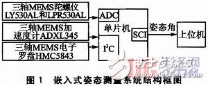
introduction
May 11, 2023