Power supply is an indispensable component of various electronic devices. Its performance is directly related to the technical specifications of electronic devices and whether it can work safely and reliably. Currently used DC power supply and switching power supply two major categories. Because the switching power supply itself consumes low energy, the power supply efficiency is doubled compared with the ordinary linear regulated power supply, and is widely used in various industries such as electronic computers, communications, and home appliances. For the wide application of switching power supply, it is necessary to understand its principle and master its development trend, which will greatly help the actual work. Switching PowerSupply (SMPS) is known as an energy-efficient power supply. It represents the development direction of regulated power supply and has become the mainstream product of regulated power supply. With the global emphasis on energy issues, the energy consumption of electronic products will become more and more prominent. How to reduce its standby power consumption and improve power supply efficiency has become an urgent problem to be solved. Although the traditional linear regulated power supply has a simple circuit structure and reliable operation, it has the disadvantages of low efficiency (only 40%-50%), large volume, large consumption of copper and iron, high operating temperature and small adjustment range. In order to improve efficiency, people have developed a switching regulator power supply, which has an efficiency of more than 85% and a wide voltage regulation range. In addition, it has the characteristics of high voltage regulation accuracy and no use of power transformers. More ideal power supply. Because of this, the switching regulator power supply has been widely used in a variety of electronic equipment, switching power supply is through the circuit control switch tube for high-speed conduction and cut-off, the conversion of direct current into high-frequency AC power is provided to the transformer for voltage transformation , thereby generating one or more sets of voltages required. Switching power supplies are classified according to the control principle. There are roughly three working modes: 1) Pulse width modulation type, referred to as pulse width modulation (PulseWidth ModulaTIon, abbreviated as PWM). Its main feature is the fixed switching frequency, the duty cycle is adjusted by changing the pulse width to achieve the purpose of voltage regulation. At its core is a pulse width modulator. The fixed switching period provides convenience for designing the filter circuit. However, its shortcoming is limited by the minimum on-time of the power switch, and the output voltage cannot be widely adjusted; in addition, the output is generally connected to a dummy load (also known as a preload) to prevent the output voltage from rising at no load. . Currently, most integrated switching power supplies use PWM. Figure 1 Modulation waveforms of two control modes 2) Pulse frequency modulation method, referred to as pulse frequency modulation (Pulse Frequency ModulaTIon, abbreviated as PFM) . Its characteristic is that the pulse width is fixed, and the duty ratio is adjusted by changing the switching frequency to achieve the purpose of voltage regulation. Its core is the pulse frequency modulator. In the circuit design, a fixed pulse width generator is used instead of the sawtooth generator in the pulse width modulator, and the voltage is utilized? A frequency converter (such as a voltage controlled oscillator VCO) changes the frequency. Its voltage regulation principle is: when the output voltage Uo rises, the pulse width of the controller output signal does not change and the period becomes longer, so that the duty ratio is reduced and Uo is lowered. The output voltage of the PFM switching power supply has a wide adjustment range, and the output terminal can be connected to a dummy load. The modulation waveforms of the PWM mode and the PFM mode are respectively shown in Figs. 1(a) and (b), tp represents the pulse width (i.e., the on-time tON of the power switch tube), and T represents the period. It is easier to see the difference between the two. But they also have something in common: (1) Both use the time ratio control (TRC) voltage regulation principle, whether it is changing tp or T, the final adjustment is the pulse duty cycle. Although the methods used are different, the control objectives are the same, which can be said to be the same. (2) When the load changes from light to heavy, or the input voltage changes from high to low, the output voltage is stabilized by increasing the pulse width and increasing the frequency, respectively. 3) Hybrid modulation mode refers to the way that the pulse width and the switching frequency are not fixed and can change each other. It belongs to the hybrid mode of PWM and PFM . It contains a pulse width modulator and a pulse frequency modulator. Since both T and T can be adjusted individually, the duty cycle can be adjusted to the widest range, making it suitable for switching power supplies with wide range of output voltages for laboratory use. The above three working methods are collectively referred to as "time ratio control" (TImeRaTIoControl, referred to as TRC). It should be noted that the pulse width modulator can be used as a separate integrated circuit (such as the UC3842 pulse width modulator) or integrated in a DC/DC converter (such as the LM2576 switching regulator IC). It can also be integrated in an AC/DC converter (such as the TOP250 monolithic switching power supply IC). Among them, the switching regulator belongs to the DC/DC power converter, and the switching power supply is generally an AC/DC power converter. The typical structure of the switching power supply is shown in Figure 2. The working principle is: the mains entering the power supply is first rectified and filtered into high-voltage direct current, and then converted into high-frequency low-voltage pulses through the switching circuit and the high-frequency switching transformer, and then rectified and The filter circuit finally outputs a low-voltage DC power supply. At the same time, there is a circuit feedback to the control circuit in the output part, and the output voltage is stabilized by controlling the PWM duty cycle. High Voltage Thick Film Resistor
High Voltage Thick Film Resistor refers to SHV cylindrical resistors (RC Series). They are suited for all high value and voltage applications. Such as High voltage power supply. X-rays equipment, High voltage multiplier, Precision divider electron microscopes, High resolution CRT displays, Automobile Electronic, .etc.
Polypropylene Film Capacitor,Power Supply Resistors,flat resistor,thick-film resistor,HV Power Resistor XIAN STATE IMPORT & EXPORT CORP. , https://www.shvcomponents.com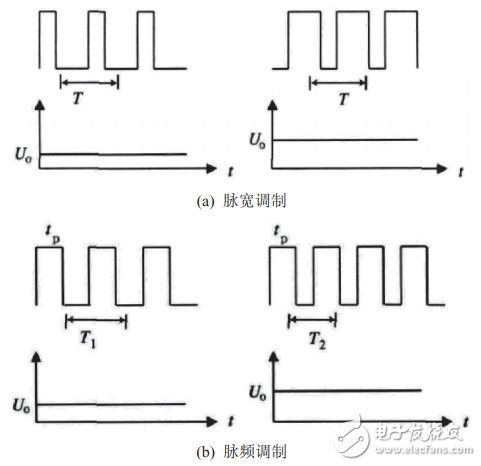
1, switching power supply overview
January 21, 2023