The secret to maintaining reliable, high-quality services in different digital TV transmission systems is to focus on the key factors that can damage the integrity of the system. This article describes these key RF measurements that can help detect problems before the viewer completely loses digital TV services and pictures.

Figure 1: With
Compared to traditional analog TV, modern digital cable, satellite and terrestrial systems are very different, and their signals are susceptible to noise, distortion and interference in the line. Today's consumers are used to watching analog TV easily. If the image quality is degraded, people usually adjust the indoor antenna to get a better image. Even if the image quality is still poor, the viewer will usually continue to watch as the program is sufficiently attractive, as long as the sound is heard.
Digital TV is not that simple. Once the reception is interrupted, the method of recovery is not always obvious. The problem may be caused by an MPEG SI or PSIP table error, or simply because the RF power is too low to reach the digital operating threshold or "spike" point. RF issues may include any of the following issues: satellite dish or low noise block converter (LNB) problems, terrestrial RF signal reflections, poor noise performance or channel interference, and cable amplifier or modulator failure.
There are several ways to solve the problem of digital TV reception. One solution is to reduce the sensitivity of the set-top box receiver to signal quality, while the more fundamental solution is that the operator should maintain a clean and high quality RF signal. To ensure this, Tektronix provides key RF measurement capabilities that integrate real-time MPEG monitoring and recording into a single MTM400 instrument. These instruments can be economically deployed at various locations throughout the transmission chain from downlink and decoding to multiplexing and re-multiplexing, ultimately through the uplink, front-end and transmitter stations. With the MTM400, operators can perform critical RF measurements at a cost equivalent to one-third of the dedicated RF test equipment. Web-based remote control allows for accurate measurements on the appropriate signal layer in the transmission chain to ensure cost-effective results.
Bit error rate BERThe bit error rate is the ratio of the number of bits in which the error occurred to the total number of bits transmitted. Early digital television surveillance receivers provided a bit error rate indication as the only measure of digital signal quality. This is easy to implement because the data is usually provided by the tuner demodulator chipset and is easy to handle. However, the tuner may often output a BER after performing forward error correction (FEC). A better way is to measure the BER before FEC so that an indication of the FEC's operation can be given. After the Viterbi de-interleaving process, Reed-Solomon (RS) decoding will correct the error bits to give a quasi-error-free signal at the output.

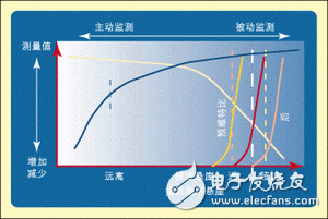
Figure 2: MER and BER before the BER increases rapidly and the viewing service is lost
This approach is feasible when the transmission system is operating away from the spikes, when only a few data errors occur and the bit error rate before Viterbi is close to zero. When the system is close to the peak, the bit error rate before Viterbi increases gradually, and the bit error rate after Viterbi increases rapidly, while the bit error rate after FEC (after RS) increases sharply. Therefore, FEC has the effect of sharpening the peak angle. As a result, a very sensitive bit error rate measurement can give an alarm, but it is usually too late to take any corrective action. Nevertheless, it is still useful to display the BER to record or quantify the quality of the transmitted signal. BER can also be used to record long-term system trends. It is best suited to identify periodic short-term signal defects.
BER measurements are usually expressed in engineering and are often shown as an instantaneous ratio and an average ratio. Typical target values ​​are 1E-09, quasi-error-free BER is 2E-04; critical BER is 1E-03; BER greater than 1E-03 will lose service.
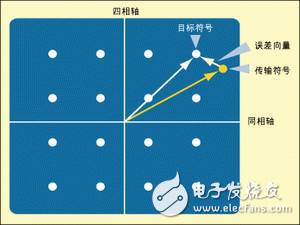
How to improve BER --- adopt MERThe TR 101 290 standard describes the measurement criteria for digital television systems. Modulation error ratio (MER) measurements are designed to provide a single quality factor for the received signal. The MER provides an early indication of the receiver's ability to correctly decode the transmitted signal. In fact, the MER compares the actual position of the received symbol (representing a digital value in the modulation pattern) to its ideal position. When the signal quality is degraded, the received symbol is farther away from the ideal position and the MER measurement will decrease.

Figure 3: Error vector.
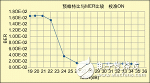
As the signal quality continues to decrease, the symbol will eventually be decoded incorrectly, and the bit error rate will increase, at which point the threshold or spike point is reached. The diagram shown in Figure 1 was obtained by connecting a MER receiver to a test modulator. After connecting, gradually introduce noise and record the BER value before MER and Viterbi. When there is no additive noise, the initial value of MER is 35 dB, and the BER is close to zero. It is worth noting that as the noise increases, the MER gradually decreases while the BER remains unchanged. When the MER reaches 26 dB, the BER begins to increase and the display is near the peak. MER shows that the signal quality of the system has been declining for a long time before reaching the peak.
The importance of MERFiber Optic Patch Panel,Fiber Patch Panel,Fiber Distribution Panel,Optical Patch Panel
Cixi Dani Plastic Products Co.,Ltd , https://www.dani-fiber-optic.com