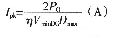
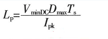
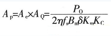
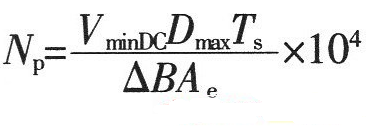
1. Maximum duty cycle Dmax of MOSFET switch operation: Where: Vor is the reflected voltage of the secondary side refracted to the primary side. When the input is AC 220V, the reflected voltage is 135V; VminDC is the lowest DC voltage after rectification; VDS is the voltage between D and S when the MOSFET power tube is turned on, Generally take 10V. 2. The peak value of the primary winding current of the transformer is IPK: Where: η is the conversion efficiency of the transformer; Po is the output rated power in W. 3. Transformer primary inductance LP is: Where: Ts is the period (s) of the switching tube; LP unit is H. 4. The air gap lg of the transformer is: Where: Ae is the effective cross-sectional area (cm2) of the magnetic core; △B is the change value of the magnetic induction intensity of the magnetic core (T); the unit of Lp is H, the unit of IPK is A, and the unit of lg is mm. 5. Transformer core Flyback converter power is usually small, generally use ferrite core as transformer core, its power capacity AP is Where: AQ is the core window area, the unit is cm2; Ae is the effective cross-sectional area of ​​the core, the unit is cm2; Po is the nominal output power of the transformer, the unit is W; fs is the switching frequency of the switch; Bm is The maximum magnetic induction strength of the magnetic core, the unit is T; δ is the current density of the coil wire, usually 200-300A/cm2, η is the conversion efficiency of the transformer; Km is the window filling coefficient, generally 0.2~0.4; KC is the core The fill factor is 1.0 for ferrite. According to the obtained AP value, a magnetic core with a slightly larger margin is selected. Generally, a relatively large magnetic core with a long window width is selected, so that the effective use coefficient of the magnetic core window is high, and the leakage inductance can be reduced. 6. Transformer primary edge number NP Where: ΔB is the magnetic induction intensity change value (T) of the magnetic core, the unit of Ae is cm2, and the unit of Ts is s. 7. Transformer secondary edge number NS Where: VD is the forward voltage drop of the secondary rectifier diode of the transformer. 8. Power switch tube selection Minimum voltage stress UDS of the switch tube Generally, a MOSFET power transistor whose breakdown voltage between DS should be slightly larger than the value calculated by equation (9) is selected. 9. Winding copper consumption PCU The primary and secondary winding resistance values ​​can be obtained by calculating the winding resistance value R. When the primary winding copper loss is obtained, the current is calculated by the primary peak current IPK; when the secondary winding copper loss is used, the current output current is used. Io to calculate. 10. Core loss Core loss is dependent on operating frequency, operating magnetic induction, circuit operating conditions, and the performance of the selected core material. For bipolar switching transformers, core loss PC: Where: Pb is the core loss (W/kg) per unit mass at the operating frequency and working magnetic induction; Gc is the core mass (Kg). For a unipolar switched transformer, since the core operates in the half of the hysteresis loop, the core loss is about half that of a bipolar switched transformer. The total transformer loss is the sum of total copper loss and core loss. Spinner Rotary Joint,Fiber Optic Rotary Joint,Rotary Union,Coaxial Rotary Joint Dongguan Oubaibo Technology Co., Ltd. , https://www.sliprob.com


January 08, 2023