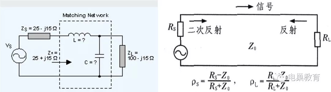
1. Signal and signal transmission 2. Impedance matching and impedance transformation network 1. Signal and signal transmission The core of the mechanical system design is the motion transformation design, which transforms and transfers simple periodic cyclic reciprocating motion into various straight or curved complex motions to achieve predetermined goals. Electronic system design uses various complex electronic circuits to complete signal conversion and transmission to achieve expected control and target results. What is a signal? The signal is the carrier of the message and the tool for carrying the message. In nature, the sound of sea tides and waves, the color change of autumn forests, and falling leaves are all signals, conveying some mysterious news that you know or don’t know. The signal is there, there can be no audience, no listeners. Even if there is, if you don’t understand the message in the signal, it’s no, right? Taking the electro-acoustic signal as an example, Chao Mei shouted "Now see you" to an object in a Shenzhen room. The common name of this object is "microphone", the technological type is called sensor, and the more detailed description is called "pickup", and the abstract name is "load". This guy with multiple names carries Chao Mei's "Now see you" voice signal, which is to be transmitted to Beijing Dianwa, thousands of miles away. Chao Mei’s voice "Now see you" is recorded from this object, and then cut and packaged for transmission. Put on a vest of various colors in the middle, after undergoing various changes, ride in different vehicles such as cars, trains, ships, etc., pass through many different types of traffic lights, and fly in the air for a while, in the middle "Thirst and hungry" need to be transferred to rest (buffer) and other processes, and transmitted to an object in the hands of Beijing Dianwa. This object may be called a "mobile phone." In the electric baby mobile phone, it undergoes a signal conversion and transmission, and finally comes to an "output load", which is connected to a thing called a "speaker", the scientific name "speaker", in which the voice of Chao Mei is restored. Despite being thousands of miles away and having gone through so many processes, Dian Ba ​​still heard the voice of Chao Mei within a few minutes. When the electric baby in Beijing heard Chao Mei’s voice, it was clear and melodious, there was no noise, and it did not become "No see you". Dianbab felt a burst of ecstasy and happiness. So, here comes the question. Chao Mei was shouting in Shenzhen. Is it true that the Beijing electric baby heard her voice? Neither is nor is it. What Chao Mei said in Shenzhen disappeared into the air after she said it. What Beijing hears is not the direct voice of Chao Mei, but the voice recorded by the electronic system, transformed and transmitted, and restored by the electronic system. However, this voice recovered in Beijing contains the inherent characteristic information of Chao Mei's speech, and it is indeed what Chao Mei said. In this example, Chao Mei’s voice is carried by the load, and the voice signal is converted into a real-time analog electrical signal, and then converted into a digital signal, which is encoded, compressed and transmitted according to the established protocol. Go to the receiving end of the electric baby, carry out the signal inverse transformation strictly according to the agreement, and reproduce it on a clear load. The signal is transmitted from Shenzhen to Beijing Dianwa’s mobile phone. But what characteristic information is conveyed in the past that can be restored in Beijing's speakers? This involves the characterization of the signal. A simple signal can be described by a certain voltage expression: instantaneous voltage, there are: Amplitude A, frequency f, phase The signal has three parameters in the time domain: frequency, amplitude and phase, and in the frequency domain there are two parameters: frequency and amplitude. If signals of many frequencies form a group, there is a concept of signal group and frequency band. The signal transmission needs to load this thing, and also needs the transmission medium. The signal can be restored not only requires Load, but also the protocol. Signal transmission and exchange are valuable. The beautiful scenery of Huangshan Mountain for thousands of years is there. Some enthusiasts have installed a lot of electronic eyes on it. As long as you pay for an account, you can send information in real time. You can see the morning and sunset of Huangshan, even a few months ago. Beautiful sight. The beauty of the mountains has always existed, and there will be no value if it is not signaled. Signal transmission always goes through various circuits. The signal is input from the beginning, and passes through a level of circuits and layers of control, and is required to be transmitted to the destination without distortion. Different parts and units in the circuit system perform their duties and faithfully complete the various transformations, control, exchange and transmission of signals. When a signal is processed through a circuit, the three parameters in the time domain will change, and the two parameters in the frequency domain will also change. These significant parameter changes are often used to characterize the functional characteristics of this circuit, such as: amplifying circuit, phase shifting circuit, oscillating circuit, etc. It can also be said that these circuits have different amplification characteristics, amplitude-frequency characteristics, phase-frequency characteristics, etc. In the above example of Chaomei and Dianwa, the signal characteristics to be transmitted to Beijing are only to transmit all the frequency components, amplitude and phase, time interval, speech rate and other parameters contained in Chaomei’s voice through the circuit system. Reproduce it in the terminal. In this example, what we must do at the beginning of the signal transmission is to transmit the instantaneous electrical power of the signal as much as possible to the following links in the circuit to ensure that it is not distorted, and then transmit it to the destination step by step. 2. Impedance matching concept Impedance matching and impedance transformation network Impedance is a physical quantity that represents the performance of a component or the electrical performance of a section of circuit. It refers to the resistance, inductance, and capacitance in the circuit that hinder the current in the circuit. Resistance (resistance) is the consumption of energy, usually converted into heat consumption, and resistance (reactance) is the storage of energy. Impedance is often expressed as Z, which is a complex number, vector vector. Mathematical formula: Impedance Z= R+i( ωL–1/(ωC)). Among them, R is the resistance, ωL is the inductive reactance, and 1/(ωC) is the capacitive reactance. (1) If (ωL–1/ωC)> 0, it is called “inductive loadâ€; (2) On the contrary, if (ωL–1/ωC) The load is a composite of three types of resistance, inductance of inductance, and capacitive reactance of capacitance, which are collectively referred to as "impedance" after the combination. When the circuit frequency satisfies ωL=1/ωC, the capacitive reactance is equal to the inductive reactance, and the circuit is resistive. This frequency point is called the resonance frequency point. Every circuit composed of inductance L and capacitance C may resonate at one or several frequencies (the point where the circuit is resistive, such as the left picture). A circuit that can resonate at one or several frequencies is called a resonant circuit. The resonant circuit is selective to the signal frequency (the picture on the right shows the characteristics of the LC parallel resonant circuit). Circuit impedance includes: source output impedance, transmission line impedance, input impedance, load impedance, etc. In order to obtain the working state of the maximum power output, impedance matching must be realized between the load impedance and the internal impedance of the excitation source. To transmit the maximum power, the impedance matching design is more complicated. For circuits with different characteristics, the matching conditions are different. In a pure resistance circuit, when the load resistance is equal to the internal resistance of the excitation source, the output power is the maximum. This working state is called matching, otherwise it is called mismatch. The condition for the maximum power of a linear circuit to transmit a signal is that the load impedance is equal to the internal resistance of the power supply. Due to the different working conditions of the non-linear circuit, the internal resistance of the signal source/excitation source fluctuates greatly, and the output impedance is not constant. It is impossible for the load end to adjust the load impedance at any time to equal the output impedance of the source to obtain the maximum power. There are two ways to set matching conditions: 1. Clarify the output characteristics of the excitation source, and the load impedance can be adjusted within the output characteristics range to obtain the approximate maximum power; 2. Determine the load conditions and adjust the excitation source so that the excitation source can always output the rated power to the load end. This is also called "matching state reached" The signal transmission link in the intermediate circuit is not always designed to transmit the maximum power. Depending on the needs, sometimes the maximum voltage or maximum current of the signal can be used to achieve the goal. For example, the output impedance of the signal source is as low as possible, and the input impedance of the signal input end of the test instrument is as high as possible (more than 10 times higher than the output impedance of the signal source), so that you can directly connect the signal source signal to the input end of the instrument to get the signal source Maximum voltage signal. In this way, there is no need to consider additional matching, and the circuit enters the expected working state, which can simplify the circuit and reduce the cost. In the signal transmission process, there must always be a specific coordination relationship between the load impedance and the output impedance of the previous stage, whether it is to transmit the maximum power or the maximum voltage or current to the next stage. Another significant function of impedance matching is to allow the downstream load to be connected without affecting the work and output of the previous stage, and to play a role in isolation. The impedance matching design for the circuit that transmits the maximum power is the most complicated. After matching the maximum power transmission, the rest is a piece of cake. Conjugate Matching and Impedance Transformation Network In the case of a given signal source, the output power depends on the ratio K of the load resistance and the internal resistance of the signal source. When the two are equal, that is, when K=1, the output power is the maximum. When the load impedance is conjugated to the signal source impedance, the maximum transmission of power can be achieved. If the load impedance does not meet the condition of conjugate matching, an impedance transformation network (also called "impedance matching network") must be added between the load and the signal source to transform the load impedance into the conjugate of the signal source impedance to realize the impedance match. There is always a third party involved between the output of the signal source and the input of the load. This third party is collectively referred to as the signal "transmission line". For example, the cables connected to the test equipment, the traces on the PCB, and twisted-pair cables are all specific forms of transmission lines. Transmission lines are an indispensable part of impedance matching networks, and they are channels for signal transmission. Therefore, the impedance matching design must select an appropriate matching method between the signal source, the transmission line/impedance matching network and the load. What are the undesirable consequences if the impedance is not matched? If it does not match, signal reflection will be formed, energy cannot be effectively transferred to the load, and efficiency will be reduced. Summary Signals are only useful if they are transmitted and exchanged: 1. The signal transmission needs to load the load, and it also needs the transmission medium. 2. The signal can be restored not only requires Load, but also protocol. 3. Signal transmission requires impedance matching between the signal source, transmission line (transmission medium), and load. Realize the purpose of effective transmission through impedance matching network. 4. Impedance transformation design involves frequency band gating, so impedance matching network design is not an easy task. In actual work, since circuit forms and devices are based on what others have used and are relatively mature, so experienced hardware experts often need to do the actual design work content is to make impedance transformation networks under various conditions Design and strive to achieve the best effect of the circuit. But they often exhausted their brains and still did not have the best results because they neglected the work of the PCB designer. Impedance matching network design is a layout-driven design work that requires the cooperation of hardware engineers and PCB designers to complete. Often novice hardware engineers do not feel that complicated, because they don’t understand but are humble, and communicate more with engineers who cooperate with upstream and downstream, so that they seem to achieve the best results easily and inadvertently. Explain again that "information exchange, sharing and cooperation create value". In order to further improve the interaction with readers and enrich the content of the official account, Mr. Hu welcomes engineers with writing hobbies to contribute to our official account backstage or add Chaomei WeChat to contribute. After the review, we will publish your article on the official account, mark your name, and you will have a chance to win God prizes~! Valve Mechanism,Valve Operating Mechanism,Overhead Valve Mechanism,Side Valve Mechanism Chongqing LDJM Engine Parts Center , http://www.ckcummins.com
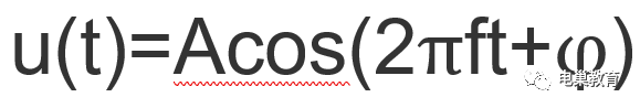
 . Signal transmission requires a load to intervene in order to show the signal. There will be instantaneous current i(t) on the load. When the signal is on the load, the instantaneous electric power is p(t)=u(t)i(t).
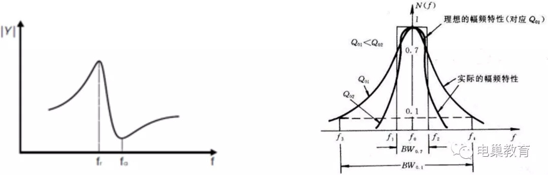

May 14, 2023