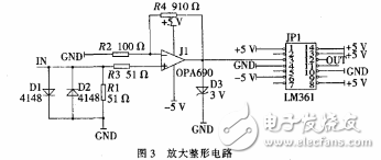
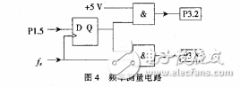
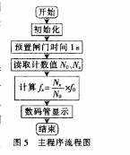
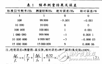
In the field of electronic technology, frequency is one of the most basic electrical parameters and one of the most basic measurements in electronic measurement. With the rapid development of science and technology, the accuracy of measuring the frequency of the measured signal is getting higher and higher. The measurement accuracy of the traditional direct frequency measurement method decreases with the decrease of the frequency of the measured signal; the accuracy of the direct measurement method decreases with the increase of the frequency of the measured signal, which has great limitations in practical applications; The equal-precision frequency measurement method not only has high frequency measurement accuracy, but also maintains constant frequency measurement accuracy in the entire frequency region. This paper introduces the design scheme of high-frequency high-precision digital frequency meter with STC12C5A60S2 microcontroller as the main control chip. Equal-precision frequency measurements, also known as multi-cycle simultaneous measurements, have the advantage of achieving the same high test accuracy and resolution over the entire frequency range compared to conventional frequency measurement principles. Its measurement principle, its working time waveform diagram. Where fx is the frequency of the input signal and f0 is the frequency of the reference signal. The two counters A and B count fx and f0 respectively in the same gate time T, the counter value of counter A is Nx=fxT, and the counter value of counter B is N0=f0T. Therefore, the frequency fx of the measured signal is: In Figure 1, the role of the D flip-flop is to synchronize the gate signal with the signal under test to achieve synchronous gate opening, and the gate open time T is exactly equal to an integer multiple of the period of the signal under test, so the counter value Nx of the counter A eliminates the traditional frequency measurement. ±1 count error in the method. Although the counter B has a ±1 count error, since f0 is very high, N0"1, the relative value of ±1 count error of N0 is small, and the error is independent of the frequency fx of the signal under test. The block diagram enables equal-precision frequency measurements over the entire frequency range. The system is mainly composed of an amplification shaping circuit, a signal frequency measuring circuit and a digital tube display circuit. The amplification shaping circuit is mainly used for performing peak-to-peak amplification processing on the measured signals (triangular wave, square wave, sine wave, sawtooth wave, etc.), and then shaping into a rectangular wave while removing noise interference. This system uses a 32 MHz quartz crystal as the reference signal to ensure the frequency measurement accuracy. 2.1 STC12C5A60S2 microcontroller When measuring high-frequency signals, since the ordinary 51 single-chip microcomputer needs 2 machine cycles, that is, 24 clock cycles, to confirm a negative transition, the maximum frequency of the external input signal is the system oscillator frequency. Assuming a 32 MHz crystal oscillator, the maximum frequency of the signal measured by the ordinary 51 MCU is 1.33 MHz. Obviously, the upper limit frequency of the signal measured by the ordinary 51 MCU is too small. In view of the above situation, the system selects the single-chip microcomputer of STC12C5A60S2 model. It is a single-clock/machine cycle (1T) single-chip microcomputer produced by Hongjing Technology. It is a new-generation 8051 single-chip microcomputer with high speed, low power consumption and super anti-interference. Its instruction set is fully compatible with the traditional 8051 instruction set, but the speed is The 8051 is 812 times, the working voltage is 3.3~5.5 V, and the working frequency range is 0~35 MHz, which is equivalent to 0~420 MHz of the ordinary 8051. There are two major advantages to using the STC12C5A60S2 microcontroller: (1) Improve the frequency measurement accuracy. The maximum operating frequency of a normal 51 MCU is 24 MHz, while the maximum operating frequency of the STC12C5A60S2 MCU is 35 MHz. The higher the operating frequency, the more the ±1/N0 of the ±1 count error of N0 tends to zero, thereby improving the frequency measurement accuracy. (2) The frequency resolution is very low. When the frequency of the signal under test is high frequency (fx≥10 MHz), the existing research schemes at home and abroad usually divide the signal to be measured and send it to the single-chip counting frequency. For example, if the frequency of the signal under test is 15 MHz, it is usually changed to 10 MHz after being divided by 10, and then sent to the MCU to count the frequency, so the frequency resolution is 10 Hz, resulting in very small measurement error. Big. The STC12C5A60S2 MCU can directly send the 15 MHz signal to the MCU to measure the frequency, which reduces the frequency resolution to 1 Hz, which greatly reduces the measurement error. 2.2 Amplification shaping circuit The amplification shaping circuit designed by the system. The input signal is first amplified by the high-precision large-bandwidth operational amplifier OPA690, and then shaped by the ultra-fast low-power precision comparator LM361, and the final output rectangular wave signal is sent to the frequency measurement circuit. The P1.5 port of the STC12C5A60S2 microcontroller is used to preset the gate pulse. The output terminal (Q terminal) of the D flip-flop outputs a synchronized gate pulse. This pulse is input to P3.2 through the AND gate, and the number of reference clock pulses in the pulse is accurately counted by the counter 0 (counter B) of the microcontroller. . The measured signal fx is simultaneously input to the CP terminal of the D flip-flop and the input terminal of the AND gate, and is output to the P3.5 port by the AND gate output terminal. The second function of the P3.5 port is defined as the number of externally counted input pulses of counter 1 (ie, counter A). At this time, the counter N counts the number Nx of signal pulses to be measured in the synchronized gate pulse. 2.3 frequency measurement circuit The frequency measurement circuit designed by this system is shown in Figure 4. 2.4 digital tube display circuit This system uses 8-bit digital tube dynamic display circuit. This circuit not only saves port resources, but also consumes very little power because only one digital tube is lit at a time. The main program flow chart of this system. Since the processor used in this system is a single clock/machine cycle (1T) STCRC5A60S2 microcontroller, it is necessary to set the corresponding register during software initialization to make it work at true 1T. 4.1 Measurement results Add +5 V voltage to the circuit and input the measured signal through the NW1640B frequency modulation and amplitude modulation function generator. The measured signal frequency is compared with the standard input signal frequency, and the recorded results are shown in Table 1. 4.2 Error Analysis The measurement error formula of the above frequency measuring method is 4.3 Measures to reduce the error Measures to reduce the error mainly include: (1) Select a crystal with high frequency and good stability. If you choose a 32 MHz crystal, you can not only expand the frequency range, but also improve the frequency measurement accuracy. (2) Appropriate expansion of the gate time can reduce the measurement error of the ultra-low frequency signal. The frequency meter designed by this system has the same frequency measurement accuracy and stability in the frequency range of 0~16 MHz. The system makes full use of the performance advantages of the STC12C5A60S2 single-chip microcomputer, which not only simplifies the circuit structure, but also reduces the cost, and has high practical value.
Features of Cotton Woven Cable Braided Sleeve
1. Totally expanded the sleeving can reach at least one point five times than the initial dimension.
2. Suitable for constructing and protecting cable harnesses or tidying cable looms.
3. Sleeve expands to allow the cables to pass through and then automatically shrinks back.
4. Multiple sizes and lengths available .
High Density Matte Solid Expandable Braided Cable Sleeving is the best sleeving out there in the market. It is the Tight, High Quality, High Density, Matte, Solid Sleeving which protects and hides wires while increasing air flow.
Application of Cotton Woven Cable Braided Sleeve
Widely used in bounding and protecting of electrical cables, automobile and aviation sectors.
It's used to cover cables, wire harnesses, tubes, industrial hoses,Automotive,Automatic equipment.
Cotton Woven Sleeve,Automotive Cable Sleeving ,Cable Management Wrap Sleeving,Blue Woven Cable Sleeve Shenzhen Huiyunhai Tech.Co.,Ltd , https://www.hyhbraidedsleeve.com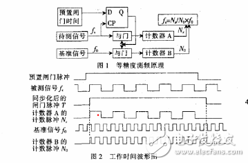
January 20, 2023