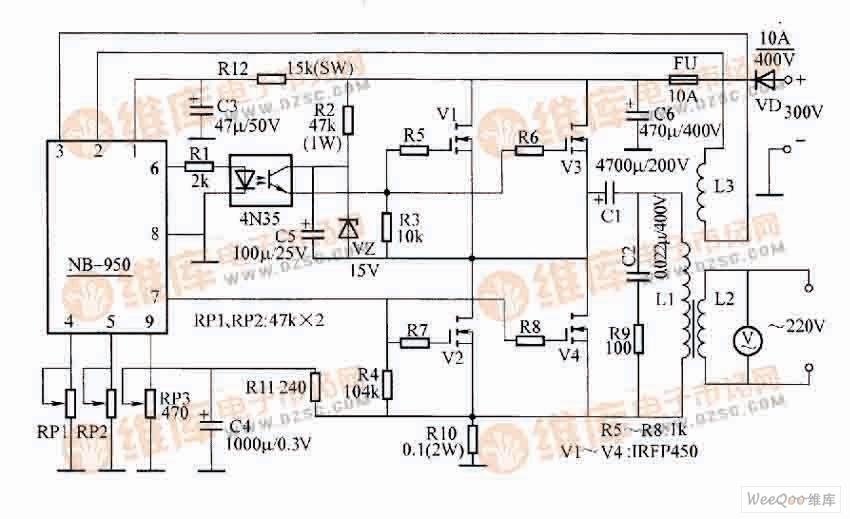
The circuit for making a 300V DC-powered 10O0W inverter is shown in the figure. High-voltage DC-powered inverter circuit Circuit working principle: Tempered Glass Screen Protector
The JJT Tempered Glass Screen Protective Film is protected by specially treated glass, and the Tempered Glass Screen Protector brings excellent scratch resistance to the screen. The Tempered Glass Protective Film is made of shockproof technology, which has the characteristics of anti-scratch, anti-fingerprint and anti-oil, which can greatly reduce the damage to the screen due to strong collision. The adhesive force of the silicon adhesive ensures that there is nothing between the screen protector and the screen, thereby improving touch sensitivity. Ultra-transparent glass can ensure a better clear image quality than ordinary Screen Protectors.
The surface hardness of the Tempered Glass Screen Protection Film is 9H, which is 4 times that of ordinary PET Film. Sharp objects (such as knives and keys) will not scratch the surface.
The Screen Protector has an "oleophobic and waterproof" coating to prevent fingerprints and other contaminants, making the screen protector easy to clean.
It has unparalleled touch and high responsiveness to touch, 99.9% transparency, transparent without bubbles.
Tempered Screen Protector, Tempered Glass Screen Protector, Tempered Glass Protective Film, Tempered Glass Film, Tempered Glass Screen Protective Film Shenzhen Jianjiantong Technology Co., Ltd. , https://www.jjttpucuttingplotter.com
In order to reduce the withstand voltage requirement of the power FET, the power stage uses a series push-pull circuit. Since the input ends of the upper and lower arms of the circuit are not common, the upper arm input end is isolated by a photocoupler. The working process is: in the negative half cycle, the signal output from the 7-pin of NB-950 drives V2 and V4 to be turned on, and the power supply E is charged to C5 through R2, V2, V4, and the charging voltage is limited to 15V by VZ; The NB-950's 6-pin signal drives the optocoupler to conduct, C5 discharges through the photocoupler and R3, and the voltage on R3 turns on V1 and V3. As a result of the two arms being turned on, a symmetrical square wave voltage having an amplitude of 1/2 E is formed on the primary winding of the output transformer T, and is supplied to the load after being raised to 220 V by the secondary winding. The supply voltage of the NB-950 is obtained by step-down of R12, which is about 30V and consumes about 18mA. In the figure, potentiometer RP1 regulates the output overvoltage protection value, RP2 regulates the output voltage, and RP3 adjusts the overload protection value. The role of VD2 is to prevent damage to the power tube when the polarity of the input power supply is reversed.
Component selection:
The optocoupler uses a model with a current transfer ratio greater than 50%. Power FETs are available with VDS > 400V, IDM > 15A, and damped diodes. The output transformer core load area S=35cm2, one L1 uses φ61.56mm enameled wire 160åŒ, the second L2 uses φ1.3mm enameled wire around 330åŒ, and the feedback winding L3 is wound around 18åŒ with φ0.51mm enameled wire.
October 09, 2022