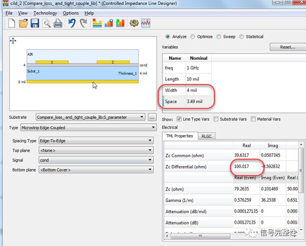
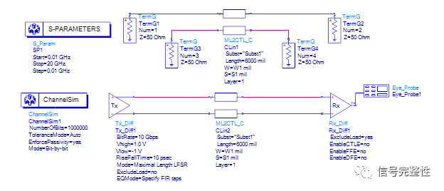
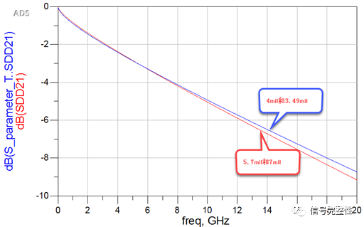
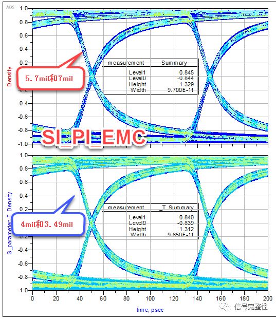
Editor's note: Two days ago, two friends were discussing whether to use tight coupling or loose coupling. They also studied some things before, but they ended up without a problem. In fact, this is a difficult question to answer. First of all, the definition of tight coupling and loose coupling is not very clear; second, the choice of loose coupling and tight coupling is not strong, because most of the product space is now more restricted . So this article is purely to do an experiment to prove some points. Time is limited, and there are still some verifications that have not been completed. Welcome everyone to discuss. For more and more high-speed signal designs, high-speed transmission lines are basically differential pairs (the upcoming DDR5 data lines are still single-ended). The advantage of the differential pair design is that the positive and negative ends are equal in amplitude and transmitted in opposite directions. When there is interference from the outside world, the positive and negative cancel each other out, so the anti-interference ability is relatively strong. In addition, the common mode noise is relatively small. The energy of external radiation is also low. In the design of high-speed circuits, there are often clear requirements for the impedance of the transmission line, such as 100 ohm. For differential pairs, there are many factors that affect the impedance, including the line width of the transmission line, the line spacing, the dielectric constant of the material, and the transmission line The distance to the reference layer and the thickness of the transmission line conductor. The figure below is a schematic diagram of the impedance calculated by ADSCILD. The parameters circled in red will affect the impedance: So if it is just to ensure impedance, there are many ways to design. Wide and narrow transmission line spacing is a very common design situation. In the above figure, the line width is 5.7 mil and the line spacing is 7 mil. Therefore, in order to ensure that the impedance remains unchanged, the line width and line spacing are modified to 4 mil and 3.49 mil, and other parameters remain unchanged. The calculated impedance is 100 ohm. As shown below: It can be seen from the above two sets of values ​​that the latter group can be regarded as tightly coupled, and the former group is loosely coupled. The following is a comparison between passive and active directions, namely, the comparison of insertion loss, eye width, and eye height. Build the schematic diagram in ADS as shown in the figure below: The length of the transmission line is 6 inches, and the simulation results are based on the two sets of values. The following figure shows the comparison result of the insertion loss: From the above figure, we can see that when the insertion loss is at low frequency, the coupling is slightly larger when the coupling is tight, and after 5GHz, the loss is a little bit smaller when the coupling is tight. The following figure shows the comparison of eye diagrams in two situations: As can be seen from the above figure, the eye width and eye height of loose coupling are a little bit larger than tight coupling, the eye height is 15mv and the eye width is 0.5ps. In summary, the loss of loose coupling is slightly larger at low frequencies (5GHz), and larger at high frequencies (over 5GHz), but the difference is a little bit; although loose coupling will be better, the difference is not much. , The loosely coupled eyes are 15mV higher. In theory, in order to ensure impedance consistency, the line width must be thinner in tight coupling, and wider in loose coupling. In tight coupling, with the higher the speed, the greater the skin effect and the greater the loss. Of course, the above are just some of the apparent results obtained from experiments. If you want to further study tight coupling and loose coupling, you can consider verifying and researching from various aspects, such as keeping the line width constant, changing the dielectric constant, and changing the line spacing. , Changes in research results, or additional radiation verification, etc. Brake Disc For TOYOTA Toyota Brake Disc,Toyota Auto Brake Disc,Toyota Car Brake Disc,Toyota Automobile Brake Disc Zhoushan Shenying Filter Manufacture Co., Ltd. , https://www.renkenfilter.com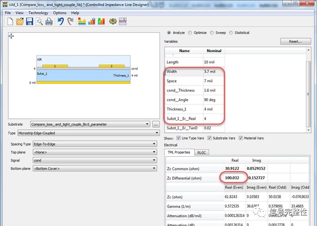
May 13, 2023