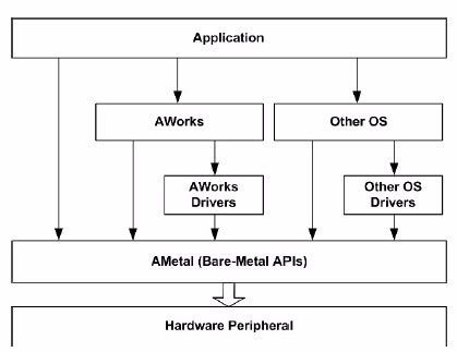
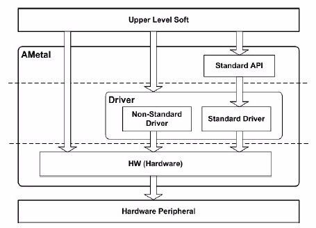
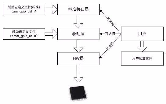
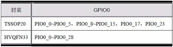
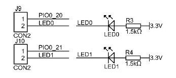
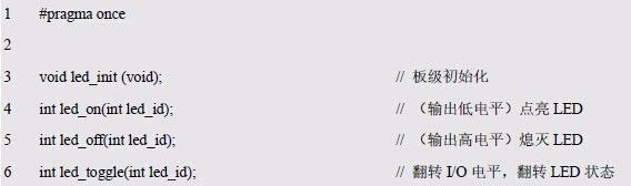
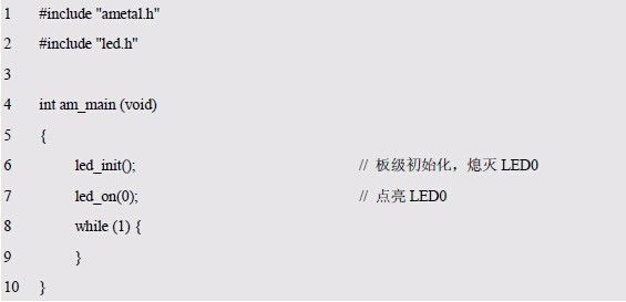
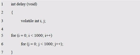
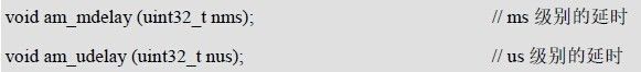
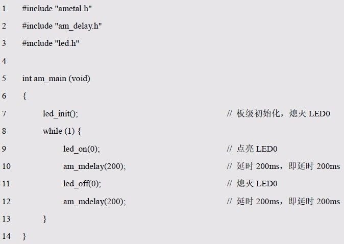
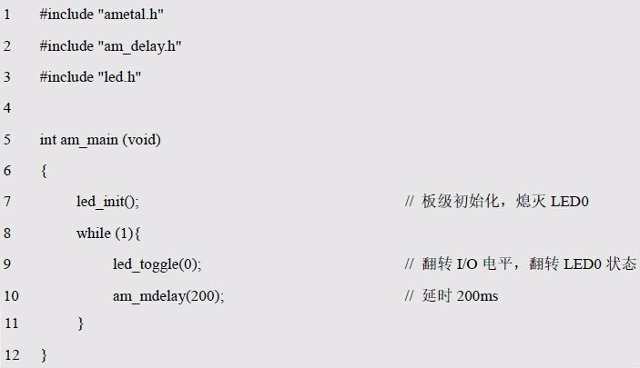
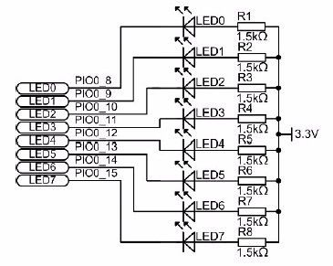
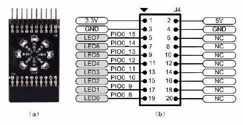
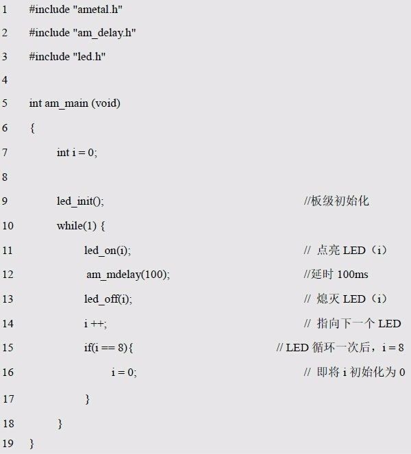
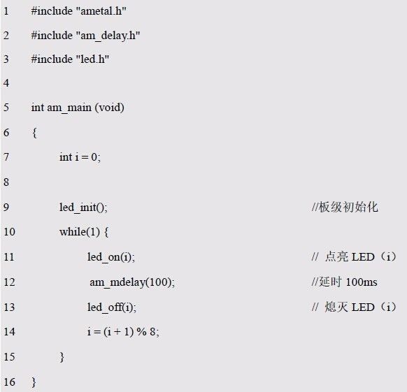
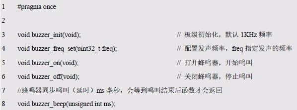
The fourth chapter is interface-oriented programming . The content of this paper includes: 4.1 platform technology, 4.2 switching signal. This chapter guides: In structured programming, since the high-level module relies on the underlying module, usually a change will cause another problem to change, and the cost of the change will rise sharply. So when introducing interfaces, an important economic consideration is the unpredictability of software, because both demand and technology are changing in an unpredictable way, with the goal of reducing dependencies. 4.1 Platform Technology > > > 4.1.1 Innovative dilemma Although the embedded system and the general-purpose computer system are the same, the embedded system has long been a relatively independent development path due to different application fields and research and development personnel. General-purpose computer software helps people solve a variety of complicated problems. As the demand increases, the problems faced are more and more complicated. The masters of the software field have conducted in-depth research and practice on these issues, so the science software engineering was born. Theory, no need to say that the development of general computer software is obvious to us. Looking back at the development of embedded systems, the demand is relatively simple. For example, through the thermal resistance sensor temperature measurement, upper and lower limit alarms and relay actions, it seems that there is no need to use complex software for embedded system application development. Engineering methods, so general computer systems and embedded systems have embarked on different development paths. When embedded systems are developed to the present day, the problems they face are becoming more and more complicated, and the programming model has not made much progress. This is the dilemma faced. I believe that everyone has felt more or less, the environment of the embedded system industry has begun to undergo fundamental changes, intelligent hardware and industrial Internet are unpredictable, and the sense of crisis arises. Although the company invested huge sums of money to build a large development team, when the product development is completed, the gross profit is not bad from the perspective of raw material BOM and manufacturing cost. After deducting R&D investment and reasonable marketing costs, the company's profits are running low. Even if employees are still dissatisfied, this is the dilemma of traditional enterprise managers. Although ZLG has invested a lot of human resources, the loss caused by repeated labor is in the billions. Thousands of MCUs, due to the lack of platform technology, even the same peripheral devices, almost have to re-write the corresponding code and documentation and test, all applications are difficult to reuse perfectly. This problem is often encountered when developing the same series of high, medium, and low-level products. The main chip may use ARM9, dual-core A9, and DSP. The operating systems are μC/OS-II, Linux, and SysBIOS. Not only is the driver code incompatible, but the application layer code is also different, and it is obviously unthinkable that the overhead was wasted on it. > > > 4.1.2 AWorks Today, with the rapid development of the MCU industry, the differences in different MCU peripherals vary widely. AWorks abstracts the same type of peripherals and designs corresponding standard interfaces and corresponding intermediate layers, so that MCU peripherals of different manufacturers and models can operate with standard interfaces. For the upper operating system, drivers need to be written for each peripheral. When writing drivers for a specific operating system, you must be familiar with specific driver platforms and operating system calls, so that programmers have to spend a lot of time learning the relevant knowledge. For the same peripheral, if you want to support multiple operating systems, you need to write multiple drivers. In fact, the underlying hardware operations are similar. AWorks is the solution to the problems mentioned here. 1. AWorks features As shown in Figure 4.1, the identifier of AWorks, which is the IoT IoT ecosystem developed by ZLG over a decade, has been successfully applied to ZLG's oscilloscopes, power meters, power analyzers, voltage monitors, and power quality analysis. A range of high performance instruments and industrial IoT products such as instrumentation, data loggers and industrial communications. Figure 4.1 AWorks Although AWorks has an embedded operating system, the operating system in AWorks is just like a driver code, just a component that can be replaced as needed. The operating system adapter resides directly on the operating system interface and is used to shield the differences between various operating systems and hardware interfaces, thus enhancing the portability and maintainability of AWorks. See Figure 4.2 for details. Figure 4.2 Relationship between AMetal and AWorks At the heart of AWorks is the development of a unified interface specification that provides a wide variety of high-quality components and graphical configuration tools "on-demand" so developers don't have to worry about the technical details associated with MCUs, peripherals, and OS. If you want to operate on the underlying hardware peripherals, you can also call the underlying interface directly. Its purpose is to achieve "one-time programming, life-long use" and "cross-platform" without relying on the specific underlying hardware, and to release programmers from the bitter sea by focusing on more competitive applications by highly reusing application software components. Business logic such as demand analysis, algorithms, and user experience. Industry partners can develop applications on the platform to collect, manage and process data via wired access and wireless access. Since all components provided by AWorks use static memory and do not use dynamic memory allocation functions such as malloc(), memory leaks are completely avoided. After the program is compiled, you can know how much memory the system needs to run. AWorks is a lightweight real-time system, all components are optimized for initialization, and the system can be started in a very short time, so in most projects, the startup time is <1s. Obviously, the real-time performance of the system is guaranteed, and the certainty is guaranteed the most. 2. AMetal features AMetal is a subset of AWorks, which is provided as an API, but does not rely on AWorks. which is: Standardize peripheral operations without the need to develop upper-level software and drivers again; AMetal is complemented by AWorks' standardized peripheral functions and can be called directly; Available as a standalone package. Its characteristics are: Amateur that can run independently, provides project templates and demos, and develops applications based on this; Open all features of the peripheral without relying on operating system services; The efficiency and change parts are placed first in the package, and can be used without the user's manual. The location of AMetal in embedded software development is shown in Figure 4.3. It is located between the underlying hardware and the upper layer software and can be called directly by the application and the operating system. AMetal consists of two parts, the AMetal API and the AMetal component. Figure 4.3 AMetal in embedded software development The AMetal API focuses on the features of the abstract MCU itself, such as GPIO, SPI, UART, I2C, etc., and programmers can no longer write peripheral device drivers by looking at the chip manual. AMetal components focus on abstract peripheral expansion interface devices such as E 2 PROM , SPI NOR Flash, PCF85063 RTC, zigbee, BLE, keyboard scanning and LED display circuits, etc. Programmers no longer need to look at schematics and write peripheral device drivers. AMetal provides not only a package of an MCU, but a set of interface specifications, so as long as the AMetal standardized interface function specification is followed, the application software can be reused regardless of whether the MCU used is ARM or DSP or other core. . The AMetal framework shown in Figure 4.4 is divided into hardware layer, driver layer and standard interface layer. The upper layer software calls the appropriate API interface according to requirements. The third layer has corresponding header files and user configuration files for the user to reference the corresponding interface. Although major semiconductor companies provide bare-metal APIs like AMetal for their respective MCUs, the APIs vary greatly for each new MCU, making it difficult to reuse applications. Figure 4.4 AMetal framework Take GPIO as an example, and give the corresponding file structure diagram. See Figure 4.5 for details. The corresponding files of AMetal are: HW layer file, driver layer file and user configuration file. In general, the HW layer provides an interface for directly manipulating hardware registers. The interface is simple to implement and is often placed in a .h file as an inline function. Therefore, the HW layer usually only contains .h files, but when certain hardware features are set. When it is more complicated, it will also provide the corresponding non-inline function, which is stored in the .c file. The driver layer acts as an intermediate layer that uses the HW layer interface to implement the interfaces defined in the standard interface layer so that users can access GPIO using standard APIs. The user profile completes the configuration of the corresponding driver, such as the number of pins. Figure 4.5 GPIO file structure The standard interface layer abstracts the operation of common peripherals and proposes a standard API interface to ensure that the behavior of the standard API is the same on different hardware. The process of using a GPIO user: first call the driver initialization function, then you only need to directly call the standard interface function when writing the application. It can be seen that the application is based on a standard API, which is independent of the hardware platform, making it easy to run on different hardware platforms. 4.2 Switching signal > > > 4.2.1 I/O Input and Output The main function of the embedded system is to monitor the real-life events. Just like a desktop computer without a monitor, printer or keyboard, the embedded system must have the ability to input and output (I/O) digital and analog signals. The number of GPIOs available for the LPC824 family of MCUs depends on the package type of the chip. See Table 4.1 for details. Table 4.1 GPIO Pins Its characteristics are: (1) Each GPIO pin can be configured as an input or output via software; (2) All GPIO pins default to input when reset; (3) The pin interrupt register allows separate setting; (4) The setting and deassertion of each pin can be independently configured. When the I/O ports of the LPC824 Series MCUs are digital, they can be configured for pull-up/pull-down, open-drain, and hysteresis modes. In the output mode, the I/O port can output high/low level regardless of which mode is configured. In the input mode, when the pin is left floating, when the I/O port is set to different modes, the situation is: (1) When set to high-impedance mode, the level of the read pin is undefined; (2) When set to the pull-up mode, the level of the read pin is high; (3) When set to pull-down mode, the level of the read pin is low; (4) When set to relay mode, if the pin is configured as an input and is not externally driven, it can keep the input pin in a known state. By default, all of the GPIO pull-up resistors are enabled except the I2C bus P0_10 and P0_11 have no programmable pull-up/pull-down resistors and relay modes. By default, each GPIO is assigned to only one and only one external pin, which is then identified by its fixed pin GPIO function. However, the switch matrix allows the internal functions to be assigned to any external pin other than the power and ground pins. These functions are called transferable functions. Some functions, such as the crystal oscillator pin (XTALIN/XTALOUT) or the analog comparator input, can only be assigned to specific external pins with appropriate electrical characteristics. These functions are called fixed pin functions. If a fixed pin function is not used, it can be replaced with any transferable function. For fixed pin analog functions, the switch matrix enables analog input or output and disables the digital port. > > > 4.2.2 New construction Before programming, you must create a project before you can download the program to the development board. Since AMetal has provided a template project, the "new project" can be copied only. The template project is the template folder located in the projects_keil5\applications directory. The new project will re-copy the folder and name it led_blinking. Then open the led_blinking folder, name the project file led_blinking, and then double-click the led_blinking.uvprojx project file to open the project. For more detailed operation, please refer to the Quick Start Guide in the supporting development materials. After opening the project, although there are many groups (user_config, user_code, etc.) on the left side of the drawing view, there are corresponding files under each group. But don't bother, just care about the main.c file under the user_code group, and add the application to the am_main() function in the file. When the MCU has nothing to do, you can't let it go, because the end of the am_main() function marks the end of the entire application, causing the MCU to run away. Therefore, there is usually a while(1) infinite loop in the am_main() function. Once the project is built, it can be programmed. > > > 4.2.3 Output Control As shown in Figure 4.6, there are two LED light-emitting diodes on the AM824-Core. The I/O pins of the MCU are connected to J9 and J10. The LED0 is connected to the PIO0_20 of the MCU through J9, and the LED1 passes the PIO0_21 of the J10 and MCU. Connected. When the I/O output is low level 0, since the LED anode is supplied with 3.3V voltage (high level 1), a potential difference is formed, so if there is current flowing, the LED light-emitting diode is turned on, that is, the LED emits light; When the /O output is high 1, the LED diode is not turned on because the potential difference cannot be formed, that is, the LED is off. Figure 4.6 Onboard LED Circuitry The function of the resistors R3 and R4 is to prevent the overcurrent from burning and the LED is burned. This is connected by the electrical characteristics of the LED and the rated current of the LED. When the voltage of the LED exceeds 1.5V, the current will increase sharply. So you must avoid this situation. In digital circuits, when the output is high, current flows to the load; when the output is low, current is drawn from the load side. The former current is called the source current, and the latter is called the sink current. Obviously, the LED can only be turned on, off and flipped. It can directly call the interface function. The contents of the led.h interface file are shown in Listing 4.1 (the specific implementation of each interface will be described in detail in Chapter 4). Listing 4.1 The led.h interface Among them, led_id is the number of the LED, and the number of the AM824-Core onboard LED is 0 and 1, respectively. In fact, the principle of dependency inversion of programming does not have to include function pointers or abstract type data. When calling led_on() and led_off() to light or extinguish the LED, the dependency inversion principle is used. It could have interacted directly with the I/O's memory map, but abstracted the direct access into an interface. Then the programming for the interface may start from lighting the LED, as shown in Listing 4.2. Listing 4.2 Lighting the LED sample program The blinking of the LED is to let the LED turn on and off, because the computer command is executed very fast, and its execution time is microsecond, so the LED is turned on and off between microseconds, and the eye does not see flicker. If you want to make your eyes see the LED flashing, you must increase the pause time of the LED on and off by nearly second. How to achieve a pause? After illuminating the LED, do not turn off the LED, but delay for a while, let "light the LED for a while, then turn off the LED." Before the experiment, we need a delay function, how is it implemented in C? Quite simply, let the MCU execute some empty loop instructions that have no practical meaning, which is equivalent to the delay. The delay example program is detailed in Listing 4.3, in which the MCU executes approximately 1000000 empty instructions. Listing 4.3 Delayed Sample Program Is such a delay function useful? Due to the different operating speeds of the MCUs, the actual delay results are different. If different delay times are required, different delay functions are required. Obviously, the delay function is not only poorly versatile, but also has an inaccurate delay time. Fortunately, AMetal provides a high-precision standard delay function using a timer, which mainly includes two delay functions. The function prototype (am_delay.h) is as follows: According to the previous idea, after lighting the lamp, delay the time for a period of time, let the "lighting state" remain for a period of time, then turn off the LED light, and then delay the time for a while, let the "off state" remain for a period of time, see the program list for details. 4.4. Listing 4.4 Single LED Flashing Sample Program (1) In fact, the blinking of the LED is the process of letting an I/O roll over. The AMetal software package provides the LED led_toggle() function for flipping the LED status. The optimized code is shown in Listing 4.5. Listing 4.5 Single LED Flashing Sample Program (2) The MiniPort-LED module integrates 8 LEDs, all of which are active low. They are controlled by PIO0_8~PIO0_15 respectively, and R1~R8 are the current limiting resistors of the LED. See Figure 4.7 for details. Figure 4.7 LED Module Circuit The LED module is connected to the AM824-Core through the MiniPort B, and the other unused I/Os are taken out through the MiniPort A (pin header) to realize horizontal stacking of the modules, which corresponds to the function of the MiniPort interface J4 of the AM824-Core. The definition is shown in Figure 4.8. Figure 4.8 LED module physical and interface definition map The following is an example of an application development method for a general function interface using an LED street lamp as an example. People often see outdoor animated ads, which are displayed from left to right for a while and from right to left for a while, which is the effect of the water light. LED street lights are now used to simulate outdoor animated ads, allowing the LEDs to rotate clockwise. Assuming power-on initialization, all GPIOs are configured as outputs and initialized to a high level, ie all LEDs are off. First, light up LED0, turn off LED0 after delay; then light up LED1, turn off LED1 after delay; then light up LED7, turn off LED7 after delay; then light up LED0, turn off LED0 after delay... ..., the cycle of the cycle has been formed, as detailed in Listing 4.6. Listing 4.6 LED Pipe Light Sample Program (1) The flow lamp experiment uses 8 LEDs of the MiniPort-LED, and the corresponding control pins are different from the control pins corresponding to the two LEDs on the AM824-Core. When using MiniPort-LED, you need to change the value corresponding to the macro USE_MINIPORT_LED in the led.h file to 1, indicating the use of MiniPort-LED. The default value for this macro is 0, using the two LED lights onboard the AM824-Core. Obviously, LED street lights are a typical "end-to-end" algorithm. Cyclic queues and ring buffers all belong to the same type of problem. This is a common software design pattern. The optimized code is shown in Listing 4.7. Listing 4.7 LED Pipe Light Sample Program (2) As shown in Figure 4.9, the passive buzzer circuit schematic diagram, as long as J7_1 and J7_2 are shorted, the buzzer is connected to PIO0_24. When PIO0_24 outputs low level, the triode is turned on to supply power to the buzzer. When PIO0_24 outputs high level, the triode is turned off and power supply to the buzzer is stopped. Therefore, it is only necessary to switch the level state of PIO0_24 in turn to control the "power on" and "power off" of the buzzer, that is, to turn the output level of PIO0_24 at a certain frequency. In fact, the sum of "on" and "off" is the oscillation period of the buzzer, and then a certain conversion can obtain the determined audio pulse frequency parameter. Thereby, a mechanical vibration sound is generated, and the buzzer sounds as long as the frequency is within the hearing range of the human ear. Figure 4.9 Buzzer circuit diagram Obviously, the buzzer can also make a fixed frequency sound by flipping the pin level and delay. If the buzzer sounds 1KHz, the period corresponding to the 1KHz frequency is: T=1/1000(s)=1(ms), since one cycle is low (on) time and high level (off) On) the sum of the time, so in one cycle, the high and low levels are maintained for 500us. It can be seen that to make the buzzer sound uninterrupted, it is only necessary to flip the output level of the pin continuously at intervals of 500us. When you need to control the buzzer, you can directly call the buzzer interface. The contents of the buzzer.h file can be found in the program list 4.8 buzzer.h interface. Listing 4.8 buzzer.h interface Buzzer_init() sets the vocal frequency to the default value: 1KHz. If you want to modify the vocal frequency to other values, such as: 2.5KHz, you should call the vocal frequency setting function, which is “buzzer_freq_set(2500);â€. See Listing 4.9 for details. Listing 4.9 Buzzer Sounding Sample Program Compared with traditional organic backsheets, what are the advantages of dual-glass modules with glass backsheets? Here are 6 reasons why: Double Glass Solar Panels, Double Glass Solar Panel Factories, Double Glass Solar Panel Price, Perc Mono Double Glass Bifacial Solar Panels, Double Glass Frameless Solar Panels Wuxi Sunket New Energy Technology Co.,Ltd , https://www.sunketsolar.com


1) High strength: The double-glass module adopts a symmetrical structure of two-sided glass, which has better mechanical strength. During the storage, transportation and installation of the module, it is not easy to cause local cracks in the cell and scratches on the backsheet;
2) Low attenuation rate: As an inorganic material, glass itself has very good weather resistance, UV resistance, sand dust, and salt mist, which can well avoid m attenuation and failure caused by its own aging;
3) High power generation efficiency: When located on sandy/concrete ground, the surface reflectance of double-sided modules is relatively high, about 20%~40%, and a bracket with a height of 1m is erected on the cement flat roof. The first-year power generation gain of dual-glass modules will be close to 10%;
4) 30-year long-term warranty: The warranty period of double-glass modules can reach 30 years, which is of great help to the improvement of the investment rate of power station. In addition, the durability and life of photovoltaic glass itself are also very long, which has certain advantages compared with photovoltaic backsheets;
5) Moderate weight, easy to handle: Compared with the traditional single-glass modules, the double-glass modules using 2+2mm glass are not much different from the former in terms of weight, and there is no obstacle for double handling;
6) Fireproof and moisture-proof, suitable for IKEA: Double-glass modules have good barrier properties, which can prevent water vapor and air from entering the module through the glass and cause attenuation, especially suitable for photovoltaic power plants at the seaside, waterside and areas with high humidity. In addition, double-glass modules also have good fire resistance, which is very suitable for residential areas, chemical plants and other areas that need to avoid fire hazards.
January 12, 2023