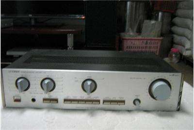
In the production test of the dynamic class A power amplifier circuit, the linearity of the dynamic bias of most circuits is not good and the offset can not be accurately controlled. However, it is successful to find another shortcut. This circuit is quite different from the traditional OCL circuit. The working principle and debugging points are introduced below. First, the circuit principle and characteristics The MOS FETs Q1, Q2 and Q4, Q5, Q9, Q10, Q11 and related components constitute a common source and a common base and a common base input stage. Q1 and Q2 convert the input voltage into a signal current, and Q4 and Q5 are set to reduce the power consumption of Q1 and Q2. Q9, Q10, Q11 are common base configuration, no current gain, can be regarded as a part of the input stage, its role is to change the direction of the signal current, the current is converted into a voltage signal direct drive output tube through R17, R18. This circuit is simple and complete, and the bipolar transistors in all channels are driven by current sources, and there are no odd harmonics that are worried about the fans. There are two main differences between this circuit and the traditional circuit: one is that the input stage uses an ultra-common large quiescent current of 30 mA per tube. The advantage is that the driving force of the output tube is strong, and the dynamics are large, the distortion is small, the linearity is good, and the curved portion of the characteristic curve of the FET is crossed. The timbre response is quite different from when using a smaller current. The author tried to reduce the current of Q1 and Q2 to 8 mA. The original round and thick tone became a bit stiff. The second is the dynamic bias circuit. The conventional OCL circuit clamps the constant voltage tube Q8 between the two base (gate) poles of the output tube, and its potential fluctuates with the output voltage, and the potential of the Q8 in the circuit is fixed, which is beneficial to improve the dynamic bias. Accuracy. In static state, the constant voltage circuit composed of Q8 and so on provides stable bias to Q6 and Q7, and adjusts W2 to change the quiescent current value. The dynamic biasing process is as follows: when the output is negative half cycle, the output signal is divided by R22 and R23, and the base of Q8 is shunted by D8, W2, and R21. The voltage across Q8 rises, the current of Q6 and Q7 rises, and the current of Q9 and Q11 rises. And further increase the output tube current. The half-wave rectification circuit composed of D8 and C12 stores the negative potential on C12 when the output is negative half cycle, providing the same offset amount for the positive half cycle output as the negative half cycle, and the time constant of C12 charging is less than its discharge. The time constant on which the voltage is relatively stable over a period of time. In this way, the circuit will automatically adjust the operating current of the final stage tube to work in the Class A state with the output voltage value. According to the load impedance value, the ratio of R22 to R23 can be reasonably selected to obtain accurate control amount and excellent dynamic bias linearity. Second, debugging points 1. Static debugging. After the installation is confirmed, the output tube is not installed first, the output terminal is short-circuited to the ground, and the power is turned on. The voltages of R17 and R18 are adjusted to be close to the threshold voltage of the output tube. The power is cut off and the power tube is installed to remove the short-circuit line. Disconnect R22, adjust W2 to make the output tube quiescent current about 250mA, adjust W1 to make the output terminal zero potential, and the heat engine will be re-adjusted for half an hour. 2. Debugging of the dynamic bias circuit. Connected to R22, the output terminal is connected with a high-power (wire-wound) resistor that is consistent with the load impedance. Note that the resistor power P ≥ V square c1/R, short circuit C6, so that the circuit becomes a DC amplifier, the output of the upper output transistor Q14 String-current meter, the output terminal is connected to a voltmeter, slowly adjust W1, so that the potential of the output terminal is gradually approached from zero to negative full-scale. The current value of Q14 should be slowly decreased with the decrease of the potential of the output terminal, but it is never cut off. For a negative full scale, the current of Q14 is more suitable at 50mA, otherwise the value of R23 should be changed. Callback W1, so that the potential of the output terminal is zero, remove the C6 short-circuit line and the output terminal dummy load, and connect the speaker to audition. Third, matters needing attention 1. +45V power supply must be regulated, otherwise the quiescent current will fluctuate with the fluctuation of the power supply voltage, positive and negative 30V power supply should be full of energy; 2.Q4, Q5, Q9, Q10, Q11 must add heat sink, I will install it On the same heat sink, the zero potential of the output is very stable by thermal coupling; 3.Q1 and Q2, Q14 and Q15 must be paired to get on the machine, and the other symmetrically used tubes can be paired best, but the requirements are not strict. 4.Q1 and Q2 can not use junction tube. Because the junction tube cross-conduction is too low, the gain of the whole machine will be seriously insufficient. If the tube is not to be connected, the resistance of R17 and R18 should be increased, and the output tube should be driven. 5. If Q3 is thermally unstable, it will cause quiescent current drift. If there is such a phenomenon, temperature compensation should be considered. 6. When soldering MOS tube, pay attention to anti-static breakdown. 7.Q1, Q2 can not be purchased when K214 can be replaced, and can cancel Q4, Q5 to make the circuit more concise. EI/ AIW Enameled Aluminium Wire
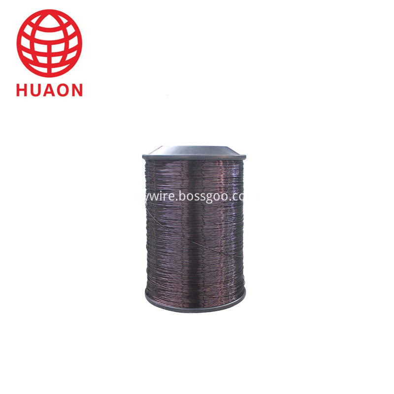
Class 200 heavy insulation thickness of Polyester-imine / polyamide-imide compound enameled aluminum round wire
Product Name
Enameled aluminium wire EI/AIW
2065-6.00,CLASS C-200
Material
Aluminium
Type
EI/AIW
Themal class
calss C -200
Country of origin
China(Mainland)
Used
motor,transformer,rectifier and such
Enameled Aluminum Wire,Ei/ Aiw Enameled Aluminium Wire,Round Winding Wire,Super Enameled Aluminum Round Wire HENAN HUAYANG ELECTRICAL TECHNOLOGY GROUP CO.,LTD , https://www.huaonwire.com
About EI/ AIW Enameled Aluminium Wire

April 02, 2023