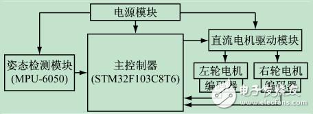
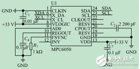
The two-wheel self-balancing trolley system is similar to the inverted pendulum system and has the characteristics of multivariable, nonlinear and strong coupling. It is an ideal platform for studying various control methods. The control process of the two-wheel self-balancing trolley system is that the microcontroller analyzes and processes the data collected by the attitude detection sensor and the encoder, and calculates the real-time control amount to restore the balance of the system, thereby driving the motor to realize the dynamic balance of the system. Aiming at the complexity of the car system, this paper proposes a method combining Kalman filter algorithm and double closed-loop PID control algorithm. The Kalman filter algorithm is used to fuse the tilt angle and angular velocity data collected by the MPU-6050 sensor to obtain the balance of the car. The optimal estimation value of the attitude is to use the attitude information and the speed as the feedback control amount to form a double closed loop PID control algorithm, and then combine the high performance STM32F103C8T6 as the main controller, thereby improving the stability and anti-interference ability of the two-wheeled trolley system. The hardware circuit block diagram of the system is shown in Figure 1. The hardware circuit is mainly composed of main controller module, attitude detection module, DC motor drive module, encoder and power module. The power module is responsible for the power supply of each module control circuit of the system. The main controller module is the control core of the system, which is used to receive the data collected by the sensor module, process and calculate the data, and output the control signal to the DC motor drive module. The attitude detection module collects the angular velocity and angular acceleration of the trolley in real time. The DC motor drive module is responsible for converting the PWM signal output by the main controller into a control signal to drive the speed and direction of the two DC motors. The encoder is responsible for measuring the speed and direction of the DC motor and feeding back the measurement data to the main controller to form a closed loop control. Figure 1 System hardware circuit block diagram The DC motor used in this system has a working voltage of 12V, so it uses three 3.7V rechargeable batteries to form a 12V DC power supply. However, the STM32 main controller and the MPU-6050 require a 3.3V DC power supply, so the LM2596SDC-DC buck module is used to obtain a 3.3V power supply. This system selects STMicroelectronics' STM32F103C8T6 as the main controller. The controller is a 32b CPU based on Cortex-M3 core. The maximum operating frequency is 72MHz. On-chip integrates 32~512kB flash memory and 6~64kB SRAM memory. On-chip integration of SPI, I2C and USART communication interfaces facilitates the acquisition of data from the MPU-6050 attitude detection sensor. It contains 7 timers that can output multiple PWM signals to enable the motor drive module to obtain a stable PWM waveform. In this system, the attitude detection module is selected by InvenSense's MPU-6050. The MPU-6050 is the world's first integrated 6-axis motion processor. It integrates 3-axis gyroscope and 3-axis accelerometer, which can accurately match the car. The attitude is detected in real time [4]. The processor's angular velocity sensing range is ±250, ±500, ±1000 and ±2000°/s, and the acceleration sensing range is ±2g, ±4g, ±8g and ±16g. The acceleration sensing range can be controlled by programming. [5]. MPU-6050 can work under different voltages, VDD supply voltage is (2.5±0.125)V, (3.0±0.15)V or (3.3±0.165)V, in this system The MPU-6050 is powered by a 3.3V DC power supply. The circuit of the MPU-6050 module is shown in Figure 2. In this system, the MPU-6050 is used as a slave. The SDA and SCL ports are used to communicate with the host STM32. The data detected by the MPU-6050 is converted by the built-in 16-bit AD converter. Then, the 16-bit digital quantity is sent to the host through the I2C bus interface. Figure 2 Circuit of the MPU-6050 module Silicone Rubber Membrane Circuit Keypad Silicone Rubber Membrane Circuit Keypad,Custom Membrane Keypad,Waterproof Membrane Keyboard,Push Button Membrane Keyboard CIXI MEMBRANE SWITCH FACTORY , https://www.cnjunma.com

introduction
February 04, 2023