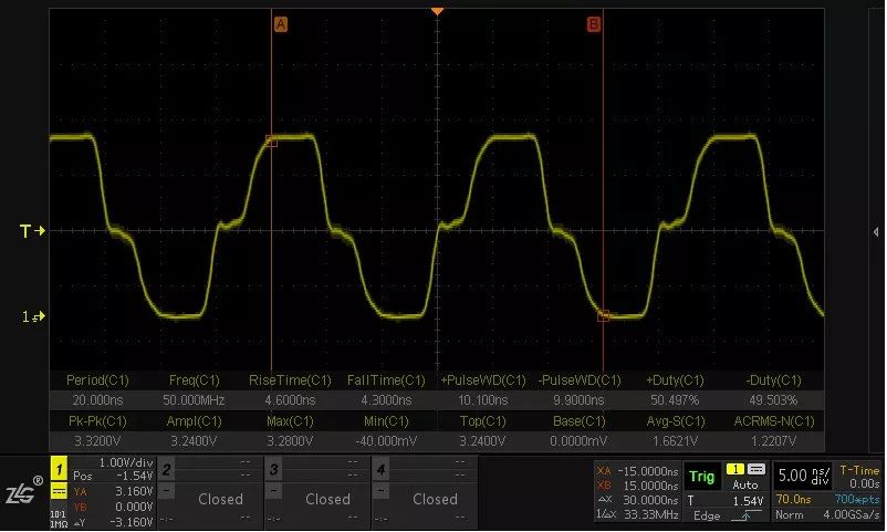
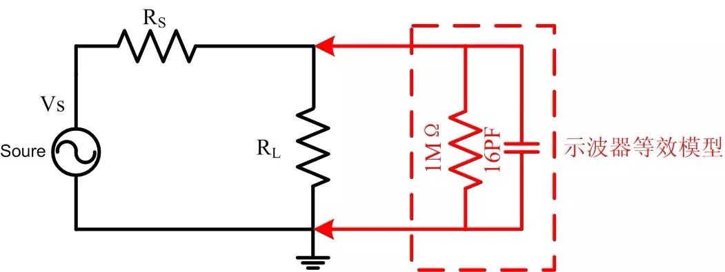
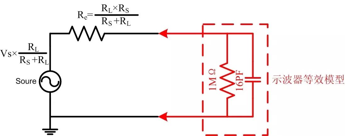
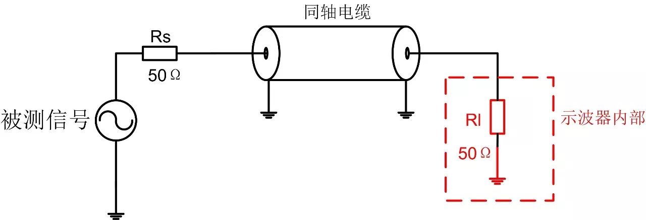
Friends who are familiar with the oscilloscope may have had such confusion: the input impedance is 1MΩ and 50Ω. How do we choose? First, the transmission line To understand the origin of 50Ω, we need to talk about the transmission line first. The electrical signal is actually propagated in the transmission line in the form of electromagnetic waves. When the size of the transmission line is no longer much smaller than the wavelength of the electromagnetic wave, the characteristics of this "wave" have to be considered. The figure below is a picture measured by the oscilloscope at the source of the signal when a narrow pulse is applied to the short-circuited network cable of the terminal of about 100 m. It can be clearly seen that there is an incident wave and a reflected wave. When the incident and reflected waves are superimposed back together, your square wave signal may be like this. How to prevent signal reflection? Just as light is reflected on the surface of the water, the electrical signal is reflected when its transmission medium changes. In order to avoid reflection on the transmission line, uniform transmission lines appear, such as PCB microstrip lines, coaxial lines, etc. They have uniform media and the same cross-sectional geometry at any point, so that the electrical signal will not be reflected in the transmission line. But once the signal comes to the end of the transmission line, is it still necessary to reflect? In fact, as long as the instantaneous impedance of the signal is kept constant, no reflection will occur. Instantaneous impedance is the impedance of an electrical signal at a certain point on the transmission line. It has been found that the instantaneous impedance of a uniform transmission line is purely resistive, independent of frequency, like a resistor, and the instantaneous impedance is only related to the geometry and filling material of the transmission line. Related, so it is called characteristic impedance. Since the instantaneous impedance is like a resistor, we connect a resistor in parallel with the load so that its resistance and characteristic impedance are equal, so that the signal is not reflected back but is absorbed by the resistor. Your circuit will be clean. This method is called terminal matching. Second, the famous 50Ω The characteristic impedance affects the electrical properties such as signal transmission power, transmission loss, crosstalk, etc., and its board and geometry affect the manufacturing cost. In this case, only a compromise can be found. And 50Ω is an optimal balance point for transmission power, transmission loss, and manufacturing cost of coaxial lines. Therefore, most high-speed signals use a 50Ω characteristic impedance system, which forms the standard and is still used today, becoming the most widely used impedance standard. For example, the common PCIE has a single-ended impedance of 50Ω. This is the origin of this 50Ω, and because of this, there will be a 50Ω impedance position on the oscilloscope. Its role is to match the transmission line in a 50Ω system. Third, the load effect of the oscilloscope Some friends may have doubts. According to the above discussion, isn't the 50Ω match better than the 1MΩ match, so what about 1MΩ impedance? This involves the load effect of the oscilloscope. I believe that everyone has this experience, debugging a problematic circuit, want to look at the waveform, the result is normal after the probe circuit is connected, and the probe circuit is removed again. This is caused by the load effect. The oscilloscope itself has an input impedance. When measuring with an oscilloscope, this part of the impedance has to be connected in parallel to the circuit. Taking the oscilloscope in the 1MΩ impedance mode as an example, it can be roughly equivalent to a form in which 1MΩ and a capacitor of a dozen pF are connected in parallel. This 1MΩ is the specification for an oscilloscope. Capacitance is a parasitic parameter that we don't want but that is inevitable. At DC and lower frequencies, 1MΩ dominates. When the frequency exceeds 10MHz, the capacitor becomes the main load. Due to the introduction of these two parameters, the signal at the time of measurement is different from the original signal, which causes an error in the measurement result. So how big is the difference, it also depends on the output resistance and load of your circuit under test. Just follow the example above. According to the Thevenin theorem, it can be changed to: As can be seen from the schematic diagram, the difference between the low-frequency signals is mainly determined by the Devining output resistance Re and the partial pressure of 1MΩ, while at high frequencies, the partial pressure of Re and 16pF capacitive reactance is required. It can be seen from the calculation that if the value of Re is 10 Ω and the frequency of the signal is 200 MHz, the load effect of the oscilloscope will cause a deviation of about -0.2 dB. And if your system's Re is 25Ω, then this deviation will reach -1dB. Therefore, if measuring high frequency signals, it is recommended to use a 10:1 passive probe for measurement, because its parasitic capacitance is lower than the oscilloscope, usually only about 9pF parasitic capacitance. 1:1 passive probes typically have a parasitic capacitance of 60pF and cannot be used to measure high frequency signals. If the 10:1 probe still does not meet your needs, measure the high frequency active probe with a smaller parasitic capacitance. What if I measure with a 50Ω impedance? Taking Re is 25 Ω as an example, the signal will be attenuated from the beginning of the DC and the attenuation will exceed -3 dB. At this point the signal has been determined to be distorted. Therefore, after the oscilloscope performs 50Ω matching, it cannot continue to test the system as a bystander. When the measured source is an unloaded signal source (such as a signal generator), the signal itself does not have a termination matching resistor. If we use 1MΩ impedance or a probe to measure, it will generate reflection at the end of the transmission line, thus interfering with the measurement signal. At this time, it is necessary to use a 50Ω impedance gear. The 50Ω resistor inside the oscilloscope can absorb the signal of the transmission line and minimize the reflected wave, so as to accurately measure the signal. The test schematic is shown below. Fourth, oscilloscope measurement and 50Ω related precautions The design starting point of 1MΩ impedance and 50Ω impedance gear is different. The starting point of 1MΩ gear is to make the oscilloscope have less load effect and can be “quiet†to be a bystander. The 50Ω gear is designed to eliminate signal reflections on the transmission line and minimize the effects of the transmission line. Which impedance position to choose depends on the actual measurement: 1. When the signal under test is a no-load signal (such as a signal generator) and a 50Ω characteristic impedance coaxial cable is connected to the oscilloscope, a 50Ω impedance gear is required. 2. When the signal under test is an onboard signal and has its own complete terminal receiving system, it needs to be directly measured with a 1MΩ impedance gear or measured with a probe. 3. When measuring with the probe, it is necessary to pay attention to the need to use 1MΩ impedance gear for passive probes. The active probes need to be matched according to the requirements of the probe. Generally, the high frequency probe requires 50Ω impedance gear, and the low frequency probe requires 1MΩ impedance gear. . 4. Note the use of passive probes. 1:1 probes typically have a bandwidth of only 6 MHz. For higher frequencies, you need a passive probe with attenuation. Huizhou Fibercan Industrial Co.Ltd , https://www.fibercannetworks.com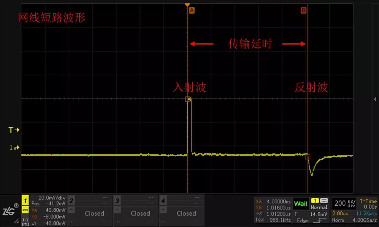
February 20, 2023