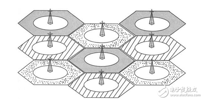
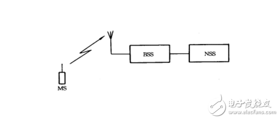
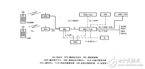
Cellular Mobile CommunicaTIon is a cellular wireless networking method that connects wirelessly between terminals and network devices to enable users to communicate with each other during activities. Its main feature is the mobility of the terminal, and it has the function of handoff and automatic roaming across the local network. The cellular mobile communication service refers to services such as voice, data, and video images provided by a cellular mobile communication network composed of devices such as a base station subsystem and a mobile switching subsystem. Cellular mobile communication classification Common cellular mobile communication systems can be divided into three categories according to their functions: macro cells, micro cells, and smart cells. Generally, these three cellular technologies have their own characteristics. 1. Macrocell technology In the cellular mobile communication system, in the initial stage of network operation, the main goal of the operator is to build a large macro cell and obtain the largest possible geographical coverage. The coverage radius of each cell of the macro cell is mostly 1km to 25km. Do it very well. Within the actual macrocell size, there are usually two special tiny areas. First, the "blind spot", due to the shadow area caused by the encounter of obstacles in the process of propagation, the communication quality of the area is seriously inferior; the second is the "hot spot", the busy area of ​​business formed due to the uneven distribution of space traffic, It supports most of the business in macro cells. The solution to the above two "points" often relies on the methods of setting up repeaters and splitting communities. In addition to economic reasons, in principle, these two methods can not be used without restrictions, because the system coverage is expanded, the communication quality is reduced; the communication quality is improved, and the capacity is often sacrificed. As the number of users increases, the macro cell performs cell splitting and becomes smaller and smaller. When the cell is small to a certain extent, the cost of building a station will increase sharply, and the reduction of the radius of the cell will also cause serious interference. On the other hand, the blind spot still exists, and the high traffic volume in the hot spot cannot be well absorbed. Microcellular technology is created to solve the above problems. 2. Microcellular technology Compared with the macro cellular technology, the microcellular technology has a small coverage, low transmission power, and convenient installation and flexibility. The coverage radius of the cell is 30m to 300m, and the base station antenna is lower than the roof height, and the propagation mainly proceeds along the line of sight of the street. The signal leaked at the top of the building. Microcells can be used as a supplement and extension of macrocells. The application of microcells has two main aspects: one is to improve coverage, and it is applied to blind spots such as subways and basements that are difficult to cover by macrocells. The second is to increase capacity. It is used in high-traffic areas such as bustling commercial streets, shopping centers, stadiums, etc. Microcells generally form a multi-layer network with macro cells when used as an application to increase network capacity. The macrocell covers a large area. As the bottom layer of the multi-layer network, the micro-cells are superimposed on the macrocell in a small area and form the upper layer of the multi-layer network. The micro-cell and the macro-cell are different in the system configuration, and are independent. Broadcast channel. The cellular mobile communication system is mainly composed of three parts: the switching network subsystem (NSS), the radio base station subsystem (BSS) and the mobile station (MS), as shown in Figure 2-1. The interface between the NSS and the BSS is an "A" interface, and the interface between the BSS and the MS is an "Um" interface. In the analog mobile communication system, the TACS specification only specifies the Um interface, and does not impose any restrictions on the A interface. Therefore, each device manufacturer adopts its own interface protocol for the A interface, and follows the TACS specification for the Um interface. That is to say, the NSS system and the BSS system can only use one manufacturer's equipment, and the MS can use different manufacturers' equipment. Figure 2-1 Composition of a cellular mobile communication system Since the GSM specification is a specification that is “fried†by some operating companies in Northern Europe, the operating company certainly prefers to spend the least investment and use the best equipment to build the best communication network. Therefore, the GSM specification has clear interfaces to the system. Provisions. In other words, each interface is an open interface. The GSM system block diagram is shown in Figure 2-2. The A interface to the right is the NSS system, which includes the Mobile Services Switching Center (MSC), the Visiting Location Register (VLR), the Home Location Register (HLR), the Authentication Center (AUC), and the mobile. The Equipment Identification Register (EIR), the A interface to the left Um interface is a BSS system, which includes a Base Station Controller (BSC) and a Base Transceiver Station (BTS). To the left of the Um interface is the mobile station part (MS), which includes a mobile terminal (MS) and a customer identification card (SIM). Figure 2-2 GSM system block diagram The GSM network is also equipped with a short message service center (SC), which can open peer-to-peer short message services, similar to digital paging services, to achieve nationwide networking, and to open broadcast public information services. In addition, it is equipped with a voice mail box to open the voice message service. When the mobile called party is temporarily unable to connect, it can receive voice mail messages, improve the network connection rate, and increase the revenue to the operation department. 2.2 Switched Network Subsystem The Switched Network Subsystem (NSS) mainly performs the database functions required for switching functions and customer data and mobility management and security management. NSS consists of a series of functional entities, each of which is described below: MSC: is the core of the GSM system. It is a functional entity that controls and completes the voice exchange of mobile stations located in the area it covers. It is also the interface between the mobile communication system and other public communication networks. It can complete functions such as network interface, common channel signaling system and billing, and can also perform handover between BSS and MSC, and assisted wireless resource management and mobility management. In addition, in order to establish call routing to the mobile station, each MS should also be able to complete the function of the ingress MSC (GMSC), that is, the function of querying the location information. VLR: is a database, which is used to store the information that the MSC needs to retrieve in order to process incoming and outgoing calls of MSs (collectively referred to as visiting customers) in the jurisdiction, such as the number of the customer, the identification of the location area, and the provision to the customer. Service and other parameters. HLR: Also a database, the data that the storage management department uses for mobile client management. Each mobile client should register with its Home Location Register (HLR), which stores two types of information: one is the parameters related to the customer; the other is information about the current location of the customer in order to establish a call route to the mobile station. For example, MSC, VLR address, etc. AUC: A functional entity for generating three parameters (random number RAND, compliant with response SRES, key Kc) for authenticating and encrypting the identity of the mobile client. EIR: Also a database that stores information about mobile device parameters. It mainly completes functions such as identification, monitoring, and blocking of mobile devices to prevent the use of illegal mobile stations. 2.3 Wireless Base Station Subsystem The BSS system is a system device that is controlled by the MSC and communicates with the MS in a certain wireless coverage area, and is mainly responsible for completing functions such as wireless transmission and reception and radio resource management. Functional entities can be divided into a base station controller (BSC) and a base transceiver station (BTS). BSC: It has the function of controlling one or more BTSs. It is mainly responsible for wireless network resource management, cell configuration data management, power control, positioning and handover, etc. It is a strong service control point. BTS: Wireless interface device, which is completely controlled by the BSC. It is mainly responsible for wireless transmission, completes wireless and wired conversion, wireless diversity, wireless channel encryption, frequency hopping and other functions. 2.4 Mobile Station The mobile station is the mobile client device part, which consists of two parts, a mobile terminal (MS) and a customer identification card (SIM). A mobile terminal is a "machine" that performs voice coding, channel coding, information encryption, information modulation and demodulation, information transmission and reception. The SIM card is the "identity card", which is similar to the IC card we use now. It is also called a smart card. It stores all the information needed to authenticate the customer and can perform some important information related to security and confidentiality to prevent illegal. The customer enters the network. The SIM card also stores management data related to the network and the customer. The mobile terminal can only access the network after inserting the SIM, but the SIM card itself is not a gold card. 2.5 Operation and Maintenance Subsystem The GSM system also has an Operation and Maintenance Subsystem (OMC), which manages and monitors the entire GSM network. It realizes functions such as monitoring, status reporting and fault diagnosis of various components in the GSM network. The interface between OMC and MSC is not yet open, as CCITT's standardization of Q3 interfaces for telecommunications network management has not been completed. External Cavity Tunable Laser,Laser Grating Sensor,Bragg Grating Stabilized Laser,Grating Stabilized Diode Laser AcePhotonics Co.,Ltd. , https://www.acephotonics.com


Cellular mobile communication
February 04, 2023