The 555 cascade timing circuit diagram is as follows. (The 555 timer is a medium-scale integrated device combining analog and digital functions. It is called 555, which is usually made by bipolar process, and is called 7555 by CMOS process, except for single timing. In addition to the corresponding dual timer 556/7556, the 555 timer has a wide supply voltage range and can operate from 4.5V to 16V, and the 7555 can operate from 3 to 18V. The output drive current is about 200mA, so its output can be compatible with TTL, CMOS or analog circuit levels. It is two timing circuits composed of two 555 time base integrated circuits, that is, delay circuits, each of which can control its own Loads such as relays also have their own delay time (determined by the values ​​of R1, C1, R2, C2), and the circuit automatically cycles when the start switch S is closed. 555 cascade timing circuit diagram The multi-speed air supply mode can bring you a comfortable and cool breeze in various scenarios. The 180° wide-angle surrounds the healthy and refreshing natural wind, and the soft wind blows on the face, returning to the natural and refreshing. The fuselage is equipped with a lanyard, so you can take the wind with you anytime anywhere. Neck Fan,Small Fan,Portable Mini Fan,Hanging Neck Fan Guangdong Aiyimi Electronic Technology Co., Ltd. , https://www.seventreasuresfan.com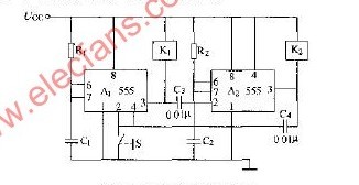
November 16, 2024