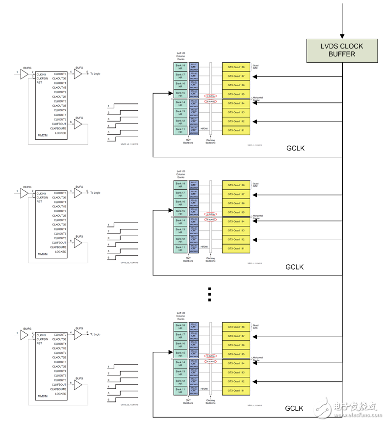
In some specific application scenarios, multi-chip serial transceiver rectification in the board needs to be supported. It is required that the data phase difference between input/output of each receiver/transmitter is small, such as 250pS. In order to meet the requirements of this specification, multi-channel phase alignment technology and input and output FIFO bypass technology must be used. The usual phase alignment technique introduces Delay_Aligner, which brings about 2~4nS phase uncertainty and cannot meet system specifications. Here is a serial transceiver rectification method that uses MMCM to achieve multi-chip phase alignment: 1) Use the circuit shown in Figure 1 to achieve global clock phase alignment between multiple chips. The circuit distributes the in-phase clock to the same global clock pin of multiple identical chips through the low Skew clock distributor on the board, and implements a zero-delay BUFG circuit by MMCM to achieve a delay of USRCLK/2 to each GT. The difference is minimal, achieving the purpose of the USRCLK/2 in-phase of the full-board GT. Figure 1. Clock architecture diagram 2) Implement TX/RXBUFFER Bypass using the Phase_Aligner of the 7 Series Tranceiver. The 7 Series GT (GTX, GTH, GTP) supports the TXBUFFER/RXBUFFER Bypass function, which adjusts the phase of the XCLK inside the Tranceiver to be in phase with TXUSRCLK or RXUSRCLK (error less than 1UI). In this way, TXUSRCLK and RXUSRCLK are in phase with all channels of the entire board (guaranteed by the clock architecture. Repeated and calibrated in the design even with errors). The specific Phase_Aligner control timing is shown in Figure 2. Figure 2. Global Clock as Phase_Aligner Control Timing Diagram for TXUSRCLK/RXUSRCLK Application case: A company needs a solution with 2048 channels and a delay difference of 250pS. The system is decomposed into 8 boards, and each board supports 128 channels. Through the backplane design, the phase of the 100MHz high quality clock arriving at each board is guaranteed to be in phase. In this way, this requirement can be achieved as long as the delay difference of each channel in the board can be controlled within 200 pS. XILINX uses this solution to achieve this requirement and meets system requirements in real-world systems. Currency Exchange Rate Display Board Currency Exchange Rate Display Board,foreign exchange rate display board,currency display board,exchange rate display board Suzhou Ribao Technology Co. Ltd. , https://www.ribaoeurope.com

February 12, 2023