(1) The power supply must have a reliable protective grounding wire, and non-professionals are prohibited from disassembling the electrical control part. (2) The surface of the instrument should be scrubbed frequently to keep it clean. When scrubbing, avoid the side of the instrument control box to prevent water from entering the instrument and damaging the instrument. (3) When the instrument is used frequently, it should be filled with an appropriate amount of grease every few months, and regularly check whether the fuse box, control components and fastening screws are loose. (4) When the brush wear of the motor causes abnormal work, the brush should be replaced in time. After the new brush is replaced, the motor must be lightly loaded at a low speed (100r/mjn) for 8h to grind the brush. After grinding, the surface of the commutator and the inner surface of the brush box are extracted with a clean gauze, and then installed. (5) When the shaker is used for a long time, when the instrument fails, it should be repaired by professional maintenance personnel and cannot be easily disassembled. (6) Remove the front and rear panels of the F section of the cabinet and check the drive belt. If the belt is too loose, loosen the motor base plate fastening studs, adjust the motor mounting base plate, make the belt moderately tensioned (not too tight), then tighten the loose bolts and test run. If the belt is worn or damaged, it must be replaced. (7) When the instrument is in the "cooling" state for a long time, it should be heated and ridiculed according to the period, and it should be done every 15d. The method is to reset the temperature to 40 °C, open the door and make the instrument work in "heating". State, each time can not be less than 4h. Make the moisture in the box fully escape. (8) When the shaker is working at high speed, in order to avoid large vibration of the instrument, the ancient culture reagent bottles should be placed symmetrically on the cradle, and the culture fluids of each bottle should be approximately equal. (9) When the instrument is not in use for a long time, especially during the rainy season or wet season, it should be energized for 5-8 hours on a regular basis (every 1 hour) to remove the moisture absorbed by the electrical components of the equipment.
Future Bus connectors Description
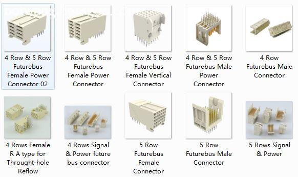
Antenk future bus connecto feature
designed in metric dirnension on 2 millimeters grid over 5 rows.
1 Standardized product through EIA (USA), IEC and CECC (international).
12 differents mating lengths on signal and 3 on power for standard connector system.
Future Bus connectors Application
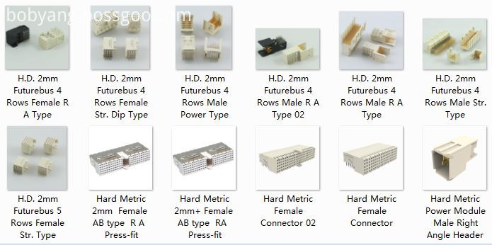
Antenk offers a complete line of 5+2 and 8+2 Hard Metric Connectors as well as a complete line of 4 and 5 row Future bus Connectors.
Vertical, 5 Rows
2mm HM (hardmetric) Connector Introduction
System designed to meet the current and future needs of instrumentation applications giving excellent electrical and mechanical characteristics. It is a high performance, high density system with flexible configuration which offers upgradeability. The connector system is fully supported by Antenk spice models to guarantee choosing the right product to match the application.
ANTENK 2.0mm HARD METRIC CONNECTOR MODULES comply with international IEC 917and IEC 61076-4-101 Metric Connectors,2.0Mm Hard Metric Connectors,Hard Metric Connectors,Hard Metric Female Connector,2.0mm Future Bus Connector Male DIP,2.0mm Future Bus Connector Female DIP ShenZhen Antenk Electronics Co,Ltd , https://www.pcbsocket.com
Future Bus connectors, which use 2mm style have a mating distance of 10mm. Both Future bus and the upgrade Future bus+ are out-dated.No additional work has been done to upgrade the specification over the years. However we still produce products which meet the Physical and Electrical layers of IEE P896.
2 Selected by IEEE as the interconnection system for Futurebus + / SCI / VicBus.
3 Multi-sources product,use for telecommunication, network, server / workstation market.
4 High tempersture materials SMT compatible.
5 Modular design giving flexibility for system design.
6 Stackable end to end without loss of contact position.
7 High density (more than 2 times as compared to the standard inch based " Euroconnector DIN 41612" ).
8 Tuning Fork female contact concept for higher robustness and improved reliability
(low contact resistance and high normal force).
9 Low insertion force design.
10 Inverse connector system (signal and power).
11 Optimized solder and compliant press-fit terminations for backplane and circuit board connectors.
Telecom backplane board

4 and 5 row Future bus Connectors
4 Rows Signal & Power
5 Rows Signal & Power
Female IDC Type 4&5 Rows
Power Connector & Cable
Shroud
Right Aangle, 5 Rows
Vertical, 4 Rows
Right Angle, 4 Rows
5+2 and 8+2 Hard Metric Connectors

2.0mm Future Bus Connector Male DIP
2.0mm Future Bus Connector Female DIP
2.0mm Future Bus Connector Male Press Fit
2.0mm Future Bus Connector Female Press Fit
2.0mm Future Bus Connector Power Type
standards. The connector systems in telecommunication and other industries require hight density connectors to support
larger amounts of data increasingly higher speeds antenk 2mm hardmetric modules offer the solution
Features and Benefits:
This high density connector modules can be stacked end to end without loss of space.
1,ANTENK developed the 2.0mm series under thorough consideration of impedance match, propagation delay,
cross talk, reflection. It is the ideal connector for digital high speed data application.
2,ANTENK offers differend types with inverted mating configuration. The male connector is a fixed module at the
backplane and the female commector is a free component of the plug-in module. The male connector has 5 signal row.
3 The outer shielding rows z and f of the male connector engage the shielding contacts of the famale connector. theshield
is also designed for gas tight, press-fit installation.
4 The connector system offers 15 contact length that utilize the proven press-fit assembly technique. Within the 15
contact length are 3 mating levels, achievable on both the plug-in and rear I / 0 side.
5 Coding system prevents mix-up and wrong mating between male and female connectors.
6 The 2.0mm hard metric connectors and DIN 41612 connectors can be used on the same PC board as both have the
same mating distance.
7 Staggered make-break pin populations for optional hot-swap capability.
8 Rear pin option for through-the-backplane I/O application.
9 High density PCI capability,shield for EMI/RFI protection.
2mm HM (hardmetric) Connector Features:
High density system with small real estate on backplane and daughtercard
Extensive range of signal, power, coaxial and fibre board-to-board and cable-to-board connections
Modular units give flexible configuration
Special versions for VME64 extensions and CompactPCI
Signal contact rating 1.5a fully energized
Universal power module rated at 7.8A/line, 23.4A fully energized
All lines impedance controlled to 50 (single ended) and 100Ω (differential) nominal
Safe design, complies with IEC950 in mated condition
Universal power module is safe in unmated condition
Several performance levels for board and cable connectors with unshielded and shielded versions
Mismatching keys block mating before any contact touch
Small press fit board hole allows maximum track width and minimum signal corruption
1.4 to 5.6mm (0.055 to 0.220 inch) Backplane thickness range
2mm HM (hardmetric) Connector Applications
Communications & Networking, Computers & Computer Peripherals, Sensing & Instrumentation
February 14, 2023