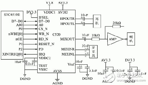
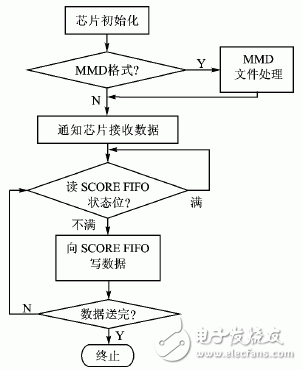
Chord is originally a concept on music theory, referring to a combination of three or more sounds stacked in a three-degree relationship. In the field of industrial design of audio equipment, chords refer to multiple sound sources and sound simultaneously. Also known as polyphony, polyphony. Polyphonic ringtones have been widely used in mobile phones. Its mellow timbre and strong three-dimensionality have completely replaced the previous monophonic ringtones. Currently, there are various file formats for polyphonic ringtones, such as MIDI, MMF, AMR, MP3, IMY, etc. Among them, MIDI is currently the most supported ringtone file format. It has a small footprint, strong performance, and has almost become the current chord. Ringtone phone standard configuration. The MIDI chord music in the mobile phone is realized by playing a MIDI music file with a highly integrated chord chip. Chord chips use the sound synthesis and tone to determine the effect of ringtone playback. The early FM (Frequency Modula-Tion) synthesis method combines the tones of multiple frequencies into a composite sound to simulate the sound of various musical instruments, resulting in less sound and poor sound quality. The other is wavetable synthesis. This method is to record the music of various real musical instruments first and then perform synthesis processing. The sound is good and the sound range is wide. According to the wave table generation methods, it is divided into software chords and hardware chords. Software chords save system overhead over hardware chords and are easier to integrate into mobile devices. At present, there are various chord control chips in the mobile phone market, such as Yamaha in Japan, Winbond in China and Wanghong in China, and China’s Weixing in the mainland. Each company's chord chips have their own characteristics, in which the smart C520 can support the national musical instrument playing, so use C520 for chord music control. C520 is a chord chip of Shanghai Zhi Duo Microelectronics Co., Ltd., which is specially used to provide clear realistic music ringtones and rich game sound effects for mobile phones. The chip integrates 64 chords, 16-tone wave table and 21 Chinese folk music, 3D stereo surround synergy MIDI synthesizer, MIDI GM preset ROM, 16-bit high-performance audio DAC and 2/4 bit ADPCM decoding And other functions. 2.1 Chip Features Compared to other cell phone chord chips on the market, the C520 has the following features: 1 The input MIDI signal can be synthesized by the on-chip music synthesizer, or the ADPCM signal input by the ADPCM demodulator can be demodulated and then output through the built-in DAC. 2 Integrated high-quality MIDI GM sound library with a capacity of up to 3 Mb; provides national instrument sound banks beyond the GM sound library, supports more than 20 kinds of national instruments such as erhu, zither, cymbals, etc.; supports multi-timbral and polyphony--simultaneously Supports 16 timbres and 64 polyphony. 3 has a number of functional ports that support mobile phone vibration drive and LCD backlight drive, can be used to play music synchronized PWM to control the seven lights. 4 The interface with the master can be a parallel interface or a serial interface; allows the chip to operate in the DAC input mode, accepts input data compatible with the universal serial DAC data format, integrates FIFOs with different input data, and operates in standby mode. Less than 50 μA. 2.2 Functional Unit The entire chip consists of IOU (I/O Interface Unit), SG (Music Synthesizer), ADEC (ADPCM Demodulator), TG (Clock Module) and ANALOG (Logic) modules. The IOU completes the interface with the external CPU, controls the internal FIFO and other functional interfaces of the chip; MIDI data forming the music and external CPU control commands to the chip are also sent through the registers in the IOU. The SG module synthesizes the MIDI data from the IOU's FIFO using wave table synthesis. ADEC receives the compressed PCM data, decodes it according to the corresponding control signal, and outputs the decoded 16-bit PCM code to the SG's DSP unit. The TG doubles the input clock and generates an internal clock. ANALOG includes a DAC and low-pass filtering and power amplification of the DAC's output signal. The internal structure of the AMP.C520 chip is shown in Figure 1. 3.1 Typical Circuit The control CPU uses Samsung's 32-bit RISC chip S3C4510B. This chip is developed specifically for embedded Ethernet applications. The core is arm7TDMI, supporting THUMB instruction set with high code density and suitable for price and power-sensitive applications. Figure 1C520 internal block diagram Figure 2 Typical Application Circuit C520 and S3C4510B can be parallel interfaces or serial interfaces, but the parallel interface has faster data transfer speed than the serial interface. Therefore, parallel interfaces are used in this design. Chip application circuit shown in Figure 2. In this circuit, CS_N of C520 is controlled by I/O P0 of S3C4510B. In fact, if the chip select signal line is sufficient, any signal line in the ROM/SRAM/Flash chip select signal Nrcs[5:0] in the S3C4510B can be selected, which can save 1 GPIO; similarly, if Do not want to control the C520 reset, you can connect its reset signal with the reset line nRESET of S3C4510B, so that S3C4510B and C520 will be reset at the same time when power is on; C520 PD pin is a low-power state control pin, "1" is the normal working state , “0†is to enter the low-power state; C520 IRQ pin is the interrupt output pin, which can connect the external interrupt request signal pin XINTREQ[0] of S3C4510B. 3.2 Chip Initialization The C520 initialization is very simple, including: 1 Set the PLL divider ratio according to the external clock. The PLL divider ratio is determined by the register CLOCK (read: 10h/write: 11h) and the register Master Clock (read: 18h/write: 19h). The internal clock frequency fsys=fclock(DN+1)/(DM+1). Among them DM is the register CLOCK[4:0], DN is the register Master clock tuning[5:0], fclock is the external input clock, the internal system clock frequency fsys must be fixed between 48 MHz and 50 MHz. 2 Open the analog module and write 0 to bit3 of the Analog Power Down (read:66h/write:67h) register. 3 Set Analog Select and select analog function according to Analog Select(read:60h/write:61h). 3.3 Play MIDI Music Files The C520 can play MIDI files in MIDI FORMAT 0 and MMD formats. The ASCII value of the first 4-byte data in the MIDI FORMAT 0 file is "MThd", and the ASCII value of the first 4-byte data in the MMD file is "MMhd". The process of sending MIDI data in these two formats is different. Before sending, the first 4 words are used according to the file. Section data to distinguish. Send a MIDI file in the MIDI FORMAT 0 format. All data in the file must be sent. The MMD format file can be divided into four blocks. Each block has 8 bytes of header data at the beginning. The ASCII code value of the first 4 bytes of the first header data part is "MMhd", the ASCII code value of the first 4 bytes of the second header data part is "MMly", and the ASCII code value of the first 4 bytes of the header data part of the 3rd block is "MMdd". The first 4 bytes of the ASCII code value of the 4th header data part is "MMex". The 5th, 6th, 7th, and 8th bytes of each header data are the length of this data (excluding the header data), the 5th byte is the low byte, and the 8th byte is the high byte, which 4 The hexadecimal data composed of bytes plus the header data length 8 is the length of this data. The header data of the MMdd block data is followed by the compressed MIDI data; the MMly block data is dedicated data for karaoke, and it is not necessary to send the block when playing MIDI; Mmex is an expansion block. Figure 3 Play MIDI file flow When MMD formatted MIDI data is sent to C520, the MMhd block is sent first, and then the MIDI data portion of the MMdd block is sent (ie, the block except the block name and the block length portion), and the MMly block is not sent. Figure 3 shows the process of playing a MIDI file. This article introduces the smart phone and chord chip C520 of Chido Micro, and gives its principle and internal structure diagram. Samsung's RISC chip S3C4510B is used as a controller to achieve chord music playback. The detailed circuit schematic and the flow of playing MIDI music files are given in the article, which can be used as a reference for the applications of chord chips in mobile products. Special equipment for university physics laboratory Teaching Equipment,Optical Bench Kit,Optical Instruments In Physics,Electrooptical Modulator Experimental Instrument Yuheng Optics Co., Ltd.(Changchun) , https://www.yhenoptics.com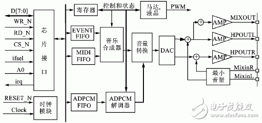
1 Polyphonic ringtones overview
April 16, 2023