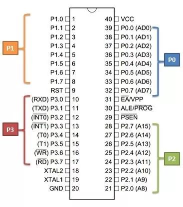
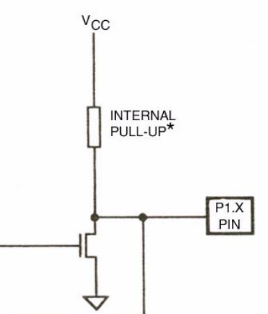
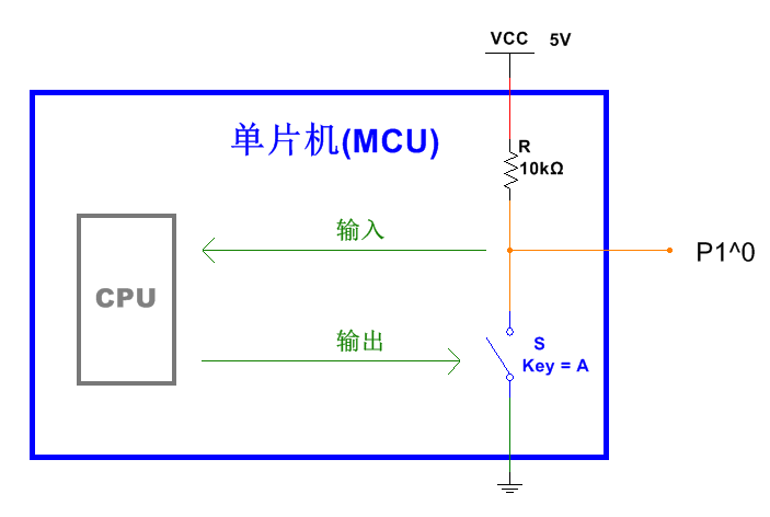
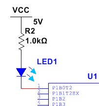
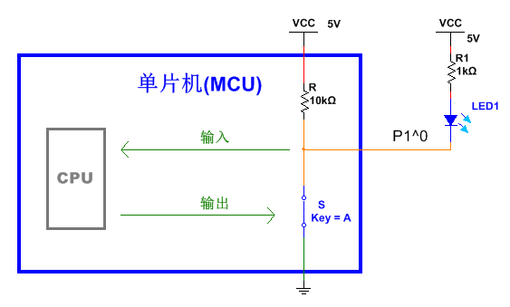
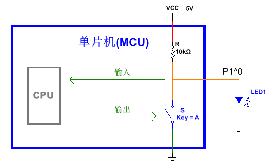
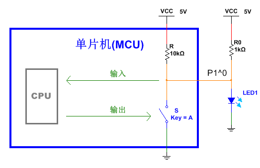
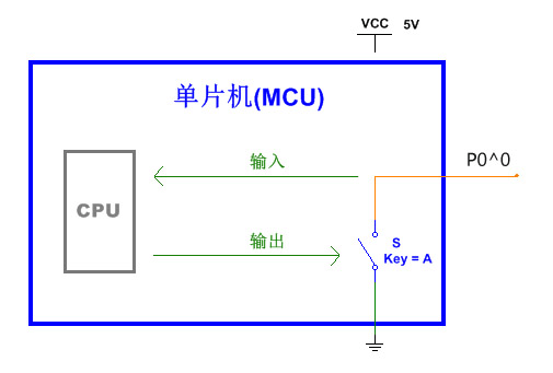
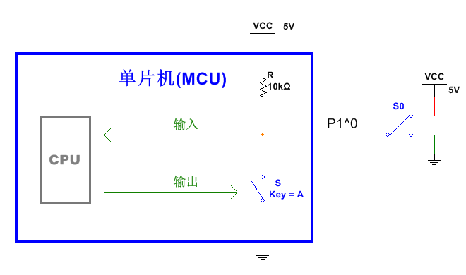
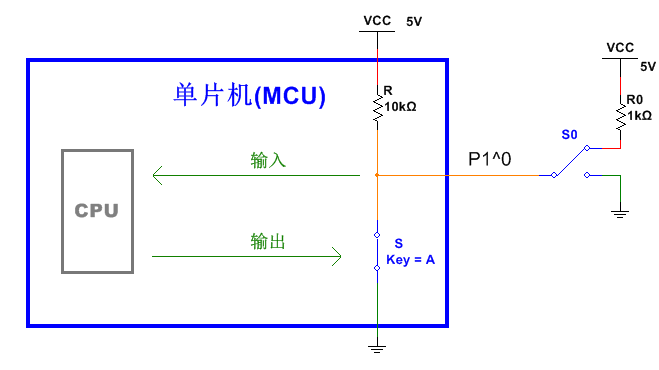
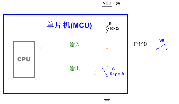
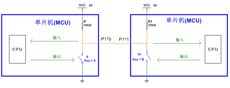
IO port operation is the most basic and most important knowledge in the practice of single-chip microcomputer. This article takes a long time to introduce the principle of IO port. I also checked a lot of information to ensure that the content was correct and took a long time to write. The principle of IO port originally needs to involve a lot of in-depth knowledge, and here is the best possible to simplify and understand. This will be of great help in solving various IO port related problems in the future. The IO port equivalent model is my original method. Through this model, it is possible to effectively reduce the difficulty of understanding the internal structure of the IO port. And confirmed by the inspection data, this model is basically consistent with the actual working principle. A lot of things have been said before, and many people may have been eager to actually operate the microcontroller. As the most important means of communication between the MCU and the outside world, the IO port is the most basic and important knowledge of MCU learning. In the previous section, we implemented the experiment of illuminating the LED with IO port. This article continues to introduce the relevant knowledge of IO port. In order to better learn the IO port operation, it is necessary to understand the internal structure and related concepts of the IO port. This knowledge is very helpful for subsequent learning, the focus is on understanding, and there is no need to deliberately remember. If you don't remember, come back and look at it. If you use it, you will remember it. We have said that the most accurate and effective way to understand a chip is to look at the official chip manual and other information. But if you start learning microcontrollers directly, it may be difficult to understand the manuals of the chip manuals, especially when you see a bunch of English, strange circuits, and terminology. If it is me, it will definitely be mad. But here I will give a picture taken from Atmel's official Atmel 8051 Microcontrollers Hardware Manual. Given this picture is not to fight everyone's enthusiasm for learning, but I hope everyone can understand how the various single-chip data we have seen come from, and whether it is accurate, all of which can be clarified through official data. Everyone will have some help in learning something in the future. The above picture is the authoritative 51-chip IO port structure diagram given by the official. It can be seen that the internal structure of the four groups of IO ports of the single-chip microcomputer are different, because some IO ports have the second function, which is mentioned in the introduction. Remember this pin chart? The second function name of the IO port is indicated in parentheses. In addition to P1, each interface has a second function. When introducing the MCU system module, I mentioned that the 51 MCU has an interface for reserving the extended memory, which is the second function of P0 and P1 in the figure (and the pins such as 29 and 30 are also used). Because there is not much use and knowledge is deeper, no specific research is done. By the way, in fact, we see AD0~AD7, which is used for parallel port. The second function of the P3 port includes the serial port, etc., and will be introduced later. Since the understanding of the principle of the IO port involves many circuits and even the knowledge of the microcomputer principle, here is only a simplified introduction, which can meet the needs of most situations. When used as a normal IO port, the working principle of the four IO ports is basically the same. The figure below is cropped from the P1 circuit in the previous figure and is the key we need to understand. The P1.X on the right indicates an IO port of P1, such as P1.0. The English written on the right side of the resistor means the internal pull-up resistor. The reason why it is called the pull-up resistor is because one end of the resistor is connected to VCC. The triangle below indicates grounding, which is equivalent to GND. In addition, the most critical one is the following. The essence of this device is the transistor, which acts as an electronic switch (if you want to know more, you can learn the analog circuit related knowledge, or wait until the principle article). The above circuit can be roughly equivalent to the following figure. Note that such a structure is just an IO port, and there are 32 such structures in the entire microcontroller. R in the figure is a pull-up resistor with a resistance of 10k, and S is an electronic switch equivalent to the previous transistor. The part of the blue box is inside the microcontroller. The switching state of S is controlled by the CPU. When the P1.0 pin is set low by the program, the electronic switch S is closed. In fact, when the electronic switch S is closed, there is a small resistance at both ends. According to the principle of voltage division, there will be a very low voltage on P1.0, which is approximately 0V, which can be regarded as low level. When the set pin is high, S is disconnected, and P1.0 is connected to VCC through a 10k pull-up resistor. If measured with a voltmeter, since the internal resistance of the voltmeter is large, it can be concluded that its voltage value is high. The procedure and circuit for lighting the first LED are described above. The procedure is as follows: #include Sbit LED = P1^0; Void main() { LED = 0; While(1); } The key part of the circuit is as follows, VCC is connected to the LED positive pole through a 1k resistor, and the LED negative pole is connected to the P1.0 port: When the microcontroller executes LED=0, the electronic switch S is closed by the CPU control, and the low level is output on P1.0. The current flows through the 1k resistor and the LED into P1.0, and then flows through S into GND, and the LED has a suitable voltage across it. Combined with the internal IO port equivalent circuit of the microcontroller, the whole circuit is as follows In the above example, P1.0 outputs a low level to illuminate the LED. Can it be reversed, P1.0 output high level LED? We can consider connecting the circuit to the following and writing LED=1 in the program. When the LED=1 is executed, S is turned off. The current flows out of P1.0 through the 10k pull-up resistor R and enters the LED. Since the resistance of the pull-up resistor is too large, the current is too small, resulting in the LED not being bright, or the brightness is very weak. So this method is usually not used. In these two methods, the former flows from the outside into the inside of the microcontroller, which we call the sink current connection; the latter has the opposite current direction, called the pull current connection. It can be seen from the comparison that for the 51 single-chip microcomputer, the sink current is relatively large, and the current sinking method is limited by the pull-up resistor, and the current is small. The maximum current sinking current in practice is also limited because the current that can pass through the electronic switch S is limited. According to the STC official chip manual, for STC microcontrollers, it is recommended that the sinking current of a single IO port does not exceed 20mA, and the sum of all IO port sink currents does not exceed 55mA, otherwise it is easy to burn the IO port. The current is only about 230uA. The current is drawn from the pull-up resistor. Can it increase the current? The answer is yes. We only need to add a pull-up resistor outside the microcontroller to increase the current and successfully illuminate the LED, as shown in the figure below. The circuit in the figure is equivalent to the parallel connection of R and R0, and the resistance of the whole pull-up resistor is reduced. But there is a flaw in doing this. In this circuit, when the microcontroller outputs a low level, S is closed, and the current flows from VCC through the pull-up resistor and S into GND. At this time, although the LED is extinguished, a large current is wasted by the pull-up resistor. Therefore, if the pull-up resistor is too large, the driving force will be insufficient, and the pull-up resistor is too small, and the power will be wasted when the output is low. What is the role of the pull-up resistor? Those who know a little more about the circuit can quickly find that if there is no pull-up resistor, the IO port can't output a high level, which is the picture below. When the switch is closed, it can output a low level, but when the switch is turned off, P1.0 is left floating and nothing is connected. At this time, the voltage of the IO port is uncertain. This state cannot judge whether it is low level or high level, which is called high impedance state. Coincidentally, the P0 port of the MCU does not have a pull-up resistor, while the other three groups of IO ports have pull-up resistors. Therefore, when P0 outputs a high level and there is no external pull-up resistor, it is a high-impedance state and cannot output a high level normally. Later, I will let everyone feel the high resistance state through specific examples. Note 1: Subsequent articles will analyze the high resistance state in detail. Note 2: Although P1.0 seems to be connected to the IO input of the CPU at the same time, that is, the green arrow with the input "input" in the figure, this part of the circuit is only turned on when the read pin is input, and It is unidirectional and can be imagined as a voltmeter input with a large internal resistance. Remark 3: As shown in the figure, the 51 MCU IO port works in the normal IO port state, and the electronic switch is realized by a transistor (including two kinds of triode and MOS tube). The level output structure implemented in the figure, if implemented by a MOS transistor, is called an open drain output (OD = Open Drain, or simply "open drain"), and the drain is a pin of the MOS transistor. Corresponds to the junction of S and R in the figure. If it is a triode implementation, it is called open collector output (OC=Open Collector), and the two principles are basically the same. Subsequent articles will introduce the triode. The presence of a pull-up resistor turns the original high-impedance state into a high level, hence the name. Corresponding to the pull-up resistor, there is also a pull-down resistor. The difference is that the other end of the pull-down resistor is not connected to VCC but to GND. The reason why the IO port is called IO port (IO=Input/Output) means that it can be both output and input. The previous one is the output of the IO port. The following is the input of the IO port. The output of the IO port is introduced by LED, and the input of the IO port is explained by the switch. In many microcontrollers, the input and output of the IO need to be switched by the circuit. For the 51 MCU, the input and output use the same set of circuits, which is the circuit we analyzed above. S0 in the figure is a single-pole double-throw switch. Switching up can connect P1.0 to VCC, and switch down to GND. When reading, the CPU will get the level on the orange wire in the figure through a specific circuit. The effect we want to achieve is to let the CPU read the level of the P1.0 port to get the state of the switch S0. When S is turned off, the CPU can know the state of the external switch S0 by acquiring the level on P1.0, thereby performing the corresponding operation. When S is closed, S0 switches down, and P1.0 is indeed low. When S is kept closed and S0 is switched up, VCC is short-circuited by directly connecting S0 and S to GND. At this time, the electronic switch S passes a large amount of current, which may burn out the microcontroller. So we added the resistor R0. S remains closed and S0 switches up. At this time, P1.0 is still low, so the CPU cannot judge the state of the external switch S0, as shown in the following figure. To sum up, when reading the IO port level, you should first set the output high level (ie, disconnect S), and then read the data. This rule applies to all IO ports. Similarly, you can also read the status of the single-pole single-throw switch (or push button switch), set the output high level before reading, the circuit diagram is as follows. The above circuit needs to rely on a pull-up resistor to work. Since the P0 port does not have a pull-up resistor, it is necessary to add a pull-up resistor externally (because if there is no pull-up resistor, and both S and S0 are turned off, the IO port becomes a high-impedance state, and the read level result is uncertain. Therefore, the switch state of S0 cannot be correctly judged). The standard two-way IO port has two features: 1. In the output mode, it can output high and low level; 2. In the input mode, if no external circuit is connected, it should exhibit a high impedance state. For the P1, P2, and P3 ports of the 51 MCU, due to the internal pull-up resistor, it is impossible to have a high-impedance state in the input mode, so it is called a quasi-bidirectional IO port. When the P0 port is operated as the IO port, if the pull-up resistor is not added, the high level cannot be output; and when the pull-up resistor is added, the high-resistance state does not appear when the input is performed, so it is also a quasi-bidirectional IO port. Remark 1: The P0 port of the 51 MCU is a bidirectional IO port if it is working in the second function state. The specific principles of the beginners do not need to be thoroughly studied. The following paragraph analyzes this and is only for reference by interested readers. Compared with the official complete IO port structure diagram, there are two upper and lower transistors inside the P0 port. When the P0 port is operating in the IO port mode, the upper transistor is turned off and can be directly ignored. The previous equivalent circuit does not consider the transistor above. When the P0 port is operating in the second functional state, both transistors can work. If the upper transistor is turned off, the lower one is turned on, and the low level is output; otherwise, the upper one is turned off, the high level is output and the pull-up resistor is not needed; if both transistors are turned off, As an input, and exhibiting a high impedance state when there is no external circuit. So it is a two-way IO port. Note 2: There is some controversy about the concept of two-way IO port and quasi-two-way IO port. The introduction here combines many aspects of the online view and is accepted by most people. What happens if I connect two microcontroller IO ports together? Below is our circuit diagram. When two IO ports are set to output low level, that is, both S and S1 are closed, the overall is low level; and when one of the IO ports is set to output low level and the other output is high level, that is, S or S1 is closed. At this time, both IO ports will exhibit a low level. Only when P1.0 and P1.1 both output high level, that is, S and S1 are both off, they will be high. It can be simply stated that two IO ports are connected together, and only when P1.0 and P1.1 are set to output high level, the two wires will appear high. This is called line and logic. Not only two, if a lot of such IO ports are connected together, only all IOs are set to output high level, and the wiring will show a high level. Lines and logic are used in the back matrix keyboard. In conclusion, the main points are as follows. The content is a bit more, but in fact only a few of them are commonly used. Again, you don't need to deliberately remember, understand the principle, and remember it when you use more. 1. The sink current can pass more current than the pull current; the LED is generally used for sinking current. 2. The smaller the pull-up resistor is, the larger the current output capability is, but the more power is discharged when the output is low. 3, before reading the IO port, you must first set the output high level 4, P0 as an output, requires an external pull-up resistor 5. When the button switch is used as an input, it is connected between the IO port and GND. In addition, a pull-up resistor is required. 6, 51 MCU's four IO ports are quasi-bidirectional in the normal IO state 7, 51 single-chip IO port compliance line and logic steel Signal Pole,Traffic Signal Pole,steel Sign Post,Monitor Pole YIXING FUTAO METAL STRUCTURAL UNIT CO.,LTD( YIXING HONGSHENGYUAN ELECTRIC POWER FACILITIES CO.,LTD.) , https://www.chinasteelpole.com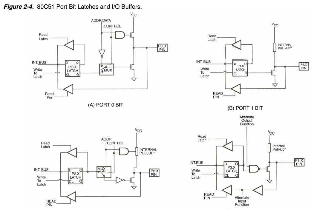

IO port equivalent circuit
Sink current and current sink
Yixing Futao Metal Structural Unit Co. Ltd. is com manded of Jiangsu Futao Group.
It is located in the beach of scenic and rich Taihu Yixing with good transport service.
The company is well equipped with advanced manufacturing facilities.
We own a large-sized numerical control hydraulic pressure folding machine with once folding length 16,000mm and the thickness 2-25mm.
We also equipped with a series of numerical control conveyor systems of flattening, cutting, folding and auto-welding, we could manufacture all kinds of steel poles and steel towers.
Our main products: high & medium mast lighting, road lighting, power poles, sight lamps, courtyard lamps, lawn lamps, traffic signal poles, monitor poles, microwave communication poles, etc. Our manufacturing process has been ISO9001 certified and we were honored with the title of the AAA grade certificate of goodwill"
Presently 95% of our products are far exported to Europe, America, Middle East, and Southeast Asia, and have enjoyed great reputation from our customers,
So we know the demand of different countries and different customers.
We are greatly honored to invite you to visit our factory and cheerfully look forward to cooperating with you.
December 30, 2022