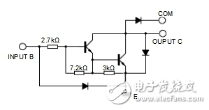
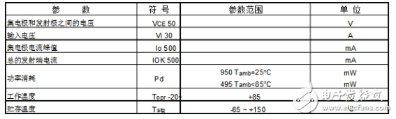
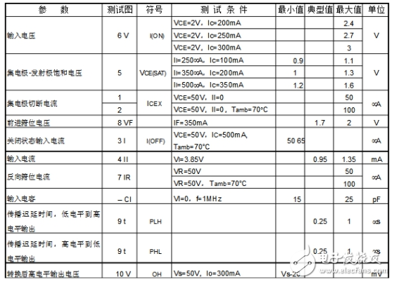
1, uln2003apg ULN2003 is a high-current drive array, which is mostly used in control circuits such as single-chip microcomputers, smart meters, PLCs, and digital output cards. It can directly drive loads such as relays. It is a high-voltage, high-current Darlington tube IC, and ULN2003APG and ULN2003 are the same series of products. High withstand voltage, high current Darlington array, composed of seven silicon NPN Darlington tubes The characteristics of this circuit are as follows: Each pair of Darlingtons in the ULN2003 is connected in series with a 2.7K base resistor. It can be directly connected to TTL and CMOS circuits at 5V operating voltage, allowing direct processing of data that would otherwise require standard logic buffers to process. ULN2003 has a high operating voltage, high operating current, sink current up to 500mA, and can withstand 50V in the off state. The output can also run in parallel at high load currents. The ULN2003 also integrates a diode with a counter-electromotive force to drive the Relay. It is a dual-row 16-pin package, NPN transistor matrix, maximum drive voltage = 50V, current = 500mA, input voltage = 5V, suitable for TTL COMS, composed of Darlington tube drive circuit. The ULN is an integrated Darlington tube IC that also integrates a diode with a counter-electromotive force. Its output allows a current of 200mA, a saturation voltage drop of about 1V, and a voltage-tolerant BVCEO of approximately 36V. The external load of the user output can be estimated based on the above parameters. The open collector output is used, and the output current is large. Therefore, it can directly drive relays or solid relays, or directly drive low-voltage bulbs. Usually, when the microcontroller is driven by ULN2003, the pull-up 2K resistor is suitable. At the same time, the COM pin should be left floating or connected to the power supply. 2, uln2003apg pin diagram and logic block diagram 1) Pin diagram and its function introduction Pin 1: CPU pulse input, port corresponds to a signal output. Pin 2: CPU pulse input. Pin 3: CPU pulse input. Pin 4: CPU pulse input. Pin 5: CPU pulse input. Pin 6: CPU pulse input. Pin 7: CPU pulse input. Pin 8: Ground. Pin 9: This pin is the common end of the internal 7 freewheeling diode negative terminals, and the positive pole of each diode is connected to the collector of each Darlington tube. When used for inductive load, the pin is connected to the positive pole of the load power supply to achieve freewheeling. If the foot is grounded, it is actually the collector of the Darlington tube that is connected to ground. Pin 10: Pulse signal output, corresponding to the 7-pin signal input. Pin 11: Pulse signal output, corresponding to the 6-pin signal input. Pin 12: Pulse signal output, corresponding to the 5-pin signal input. Pin 13: Pulse signal output, corresponding to the 4-pin signal input. Pin 14: Pulse signal output, corresponding to the 3-pin signal input. Pin 15: Pulse signal output, corresponding to the 2-pin signal input. Pin 16: Pulse signal output, corresponding to the 1-pin signal input. 2) Logical block diagram 3. Main features: 1) 500mA rated collector current (single output) 2) High voltage output: 50V 3) Input and various logic types are compatible 4) Relay driver 4, the limit parameters (Tamb = 25 ° C) 5, electrical characteristics parameters High Voltage Dc Contactor,Epoxy Seal Contactor,High Voltage Contactor Relay,Dc Switching Contactor NanJing QUANNING electric Co.,Ltd , https://www.quanningtrading.com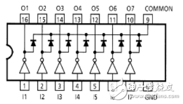
December 31, 2022