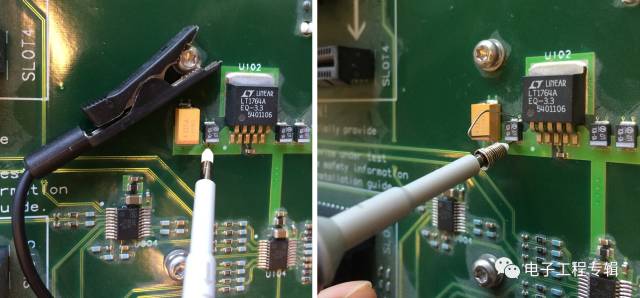
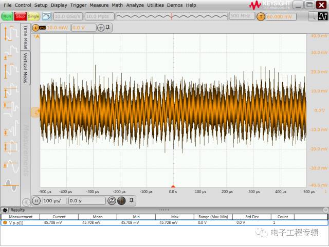
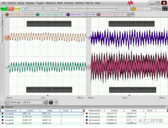
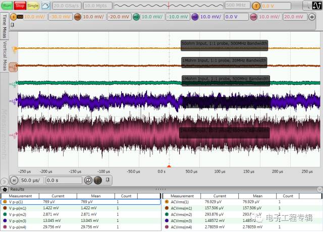
When a user tests the ripple of the 5V signal output from a switching power supply with a 500MHz bandwidth oscilloscope, it is found that the peak-to-peak value of ripple and noise has reached more than 900mV (as shown in the figure below), and the switching power supply has a nominal pattern. The peak-to-peak value of the wave is <20mv. Although the LDO of the user circuit board also regulates the output of the switching power supply, the user thinks that the measured result is too large and not very reliable, and hopes to find out the problem. problem analysis The problem of excessive power supply ripple testing is usually related to the probe used and the way the front end is connected. Firstly, the connection mode of the user probe was checked, and it was found that the long crocodile clip ground wire as shown in the left figure below was used, and the grounding point was clamped on the fixing screw of the single board, and the whole ground loop was relatively large. Since the large ground loop introduces more space electromagnetic radiation noise and ground loop noise caused by the switching power supply, it is replaced with a short ground spring pin as shown in the right figure below. After actual testing, it was found that the peak-to-peak value of the measured ripple noise was greatly improved, as shown in the following figure. However, the peak-to-peak value of ripple noise still has more than 40 mV, which is still quite different from the <20mV of the switching power supply factory. Further check the model of the probe used by the user and found that the user is using a 10:1 passive probe as standard with the oscilloscope. As shown below. The 10:1 probe will attenuate the measured signal by a factor of 10 and send it to the oscilloscope. The oscilloscope will then perform a 10x mathematical amplification of the signal under test. The advantage of this type of probe is that the probe bandwidth can be increased to several hundred MHz by the previous matching circuit, and the range of the oscilloscope is extended, but the measurement of small signals is not particularly advantageous. If the amplitude of the measured signal itself is small, then attenuating 10 times may be submerged in the bottom noise of the oscilloscope. Even if the mathematical amplification is 10 times, the signal-to-noise ratio itself is not improved. Therefore, for the measurement of power supply ripple noise, try to use a probe with a small attenuation ratio, such as a 1:1 probe. So I found another 1:1 passive probe. Although the 1:1 passive probe has a low bandwidth (usually tens of MHz), the attenuation ratio is small, which is very suitable for small signal testing. The figure below shows the comparison test results with a 10:1 probe with different bandwidth limitations after switching to a 1:1 passive probe. It can be seen that after using the 1:1 probe and setting the 20MHz bandwidth limit, the peak-to-peak value of the measured ripple noise is less than 10mV, which is far better than the test result of the 10:1 probe. A clear ripple waveform can be seen from the 1:1 probe test results and meets the user's expectations for power supply ripple noise <20mV. In addition, we can also see that the bandwidth limitation also has a certain improvement effect on the peak-to-peak noise. conclusion of issue This is a typical power supply ripple test problem. We have improved the ripple noise test results by using short ground connections, switching to low attenuation ratio probes, and bandwidth limiting. In general, the factors affecting the power ripple test results are mainly as follows: 1. Length of front-end cable and ground loop: Long ground loop picks up more electromagnetic radiation from the switching power supply and ground noise, so it is necessary to use the shortest possible ground connection. 2, the attenuation ratio of the probe: the probe with large attenuation ratio will make the small signal amplitude weaker, even submerged in the bottom noise of the oscilloscope, so you should try to use the probe with 1:1 attenuation ratio. 3. Bandwidth Limit: Many electromagnetic noises and the bottom noise of the oscilloscope are broadband. Setting the appropriate bandwidth limit can filter out additional noise. Many power supply ripple noise test scenarios use a 20MHz bandwidth limit, and some chips require 80MHz or 200MHz. 4. Measurement range: The power ripple is usually tested in a small range (such as 10mv/div or 20mv/div). The larger the range is, the higher the bottom noise of the oscilloscope. However, some oscilloscopes have a limited offset range. When the small scale is used, it may not be able to pull the measured DC voltage signal back to the center of the screen for measurement. Therefore, the oscilloscope's AC coupling function is often used to isolate the DC and then perform the measurement. Ripple noise test. 5, input impedance: Many oscilloscopes have 50 ohm and 1M ohm input impedance selection, usually 50 ohm input impedance oscilloscope bottom noise is lower. However, when the oscilloscope is connected to most passive probes, it automatically switches the impedance to 1M ohm. It can be set to 50 ohm input impedance only when connected to an active probe or coaxial cable. Before actually testing, it is a good practice to check the underlying noise of the currently used device and the system under setup. The five waveforms in the figure below are the bottom noise results for using a 500M S-Series oscilloscope with different probe and bandwidth settings. The waveforms from top to bottom are: 50 ohm input impedance, 1:1 probe, 500MHz bandwidth; 1M ohm input impedance, 1:1 probe, 20MHz bandwidth; 1M ohm input impedance, 1:1 probe, 500MHz bandwidth; 1M ohm input Impedance, 10:1 probe, 20MHz bandwidth; 1M ohm input impedance, 10:1 probe, 500MHz bandwidth. The peak-to-peak value of the bottom noise is from less than 1mV until it is close to 30mV. The importance of the probe, bandwidth, and input impedance settings during the test can be seen. If you do not have a suitable probe with a low attenuation ratio at hand, you can also make a probe with the 50 ohm coaxial cable as follows. In fact, one end of the cable is connected to the oscilloscope, the oscilloscope is set to 50 ohm input impedance; the other end of the cable is stripped, the shield is soldered to the ground of the circuit under test, and the center conductor is connected to the measured power signal through a DC blocking capacitor. The advantage of this method is low cost, low attenuation ratio, and the disadvantage is that the consistency is not good, and the parameters of the blocking capacitance and the bandwidth are not well controlled. In addition, in recent years, oscilloscope manufacturers have also introduced probes specifically designed for power supply ripple testing, combining low attenuation ratio (1.1:1), high bandwidth (hardware 2GHz, software-set bandwidth limit), both measurement needs and noise. Impedance matching (the probe itself has a DC input impedance of 50k ohms, but the oscilloscope side is a 50 ohm input impedance spectrum), a short ground (a solder front that provides very low loop inductance), a large offset range (can be up to ±24V), The advantages of simultaneous detection of ripple and DC voltage are suitable for users with high requirements for power supply ripple measurement. Stainless Steel Stretch Belt,Stainless Steel Strip Coil Belt,Stainless Steel Conveying Belt,Belt Conveyor Food Industry ShenZhen Haofa Metal Precision Parts Technology Co., Ltd. , https://www.haofametal.com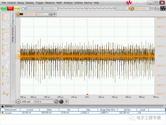

February 04, 2023