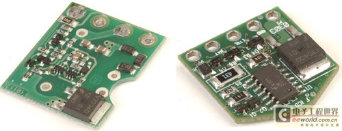
Application of Intelligent IGBT in Automobile Ignition System To generate sparks, the devices you need include a power supply, a battery, a transformer (that is, an ignition coil), and a switch to control the primary current of the transformer. Electronic textbooks tell us that V = Ldi / dt. Therefore, if the current in the primary winding of the coil changes instantaneously (that is, the di / dt value is large), high voltage will be generated on the primary winding. If the turn ratio of the ignition coil is N, the primary voltage can be amplified according to the winding turns ratio. The result is that a voltage of 10 kV to 20 kV will be generated on the secondary, across the spark plug gap. Once this voltage exceeds the dielectric constant of the air surrounding the gap, it will break through the gap and form a spark. This spark ignites the mixture of fuel and air, thereby generating the energy required for engine operation (Figure 1). Figure 1: Schematic diagram of automobile ignition system architecture Except for diesel engines, all internal combustion engines have a basic circuit (automotive ignition system). The switching elements used for charging the ignition coil have undergone great evolution: from a single mechanical switch, multiple breaker contacts in the distributor, to high-voltage Darlington bipolar installed in the distributor or in a separate electronic control module The transistor, then the insulated gate bipolar transistor (IGBT) installed directly in the ignition coil on the spark plug, and finally the smart IGBT installed directly in the ignition coil on the spark plug. Many years ago, IGBTs have become switches in ignition applications. Figure 2 shows a cross-sectional view of the IGBT. Compared with other technologies, IGBT has the following important advantages: The saturation voltage under high current is reduced; It is easy to construct a circuit that can handle high-voltage coils (400 ~ 600V); Simplified MOS drive capability; Can withstand high energy consumption when the coil is abnormally working (within the SCIS rated range). The schematic diagram of the ignition IGBT shown in Figure 2 includes several additional important elements. The collector-to-gate avalanche diode stack establishes a "turn-on" voltage. When the collector is forced to this voltage by a flyback or spike from the coil, the IGBT will turn on and the IGBT will consume it in the active area The residual energy accumulated in the coil at the time (instead of using it to generate sparks). With this avalanche "clamp" circuit, the IGBT can limit the clamping voltage to be far below the breakdown voltage of the N-type epitaxial doped / P-based semiconductor to ensure its safety run. This can significantly improve the ignition IGBT's ability to withstand the self-clamped inductive switch (SCIS) energy. And this bearing capacity is a rated index, that is, the energy absorbed by the IGBT each time the energy in the ignition coil is released as a spark. By limiting the voltage on the primary coil, the ignition coil itself is also protected from overvoltage. Figure 2: Sectional view of IGBT The latest generation of ignited IGBTs has been able to greatly reduce the die area in IGBTs and still maintain excellent SCIS capabilities. This progress is spawning multi-die smart IGBT products. Such smart products combine high-performance BCD IC technology with high-performance power discrete components IGBT. The demand motivation of the intelligent IGBT coil drive circuit lies in: the development direction of the power switch is changed from an external engine control module to a component directly located in the ignition coil on the spark plug in the engine. When the ignition coil is located on the spark plug, this structure is called "coil on plug"; when the coil drive circuit is included in the coil, this structure is called "switch on coil". The "switch on the coil" structure has significant advantages in terms of system performance, reliability, and cost. Some of its advantages are as follows: No high-pressure spark plug wire is required; No heat is generated in the engine control module; Save space in the engine control module; The actual spark generation can be monitored to improve engine control. The last performance advantage has inspired the demand for smart IGBTs. Therefore, the function of the car's ignition switch is evolving into a smart device that can monitor the spark condition, take current limiting measures to protect the coil, and can also transmit the ignition status of the engine to the engine control system. Ideal smart IGBT function in "switch on coil" applications 1. The signal interface of the engine control module. There are many problems in driving the "switch on the coil" smart IGBT by the engine control module. The electrical environment under the hood is very noisy. The signal interface of the engine control module not only needs to deal with these noises, but also has to solve the potential problem of the connection of several meters in length between the engine control module and the coil position. Electrical noise may come from EMI radiated signal noise, or it may be magnetic induction noise caused by large currents in adjacent lines. In addition to the above noise problems, there is a voltage difference of several volts between the actual ground reference point of the engine control module and the ground point where the coil or engine is located. Therefore, the defined interface between the engine control module and the intelligent ignition coil drive circuit must be able to deal with these problems. 2. Protect the ignition coil. The input signal in Figure 3 commands the IGBT to start charging the ignition coil. Under normal circumstances, when the coil stops charging and releases the spark, the current will reach 7 ~ 10A. However, when the engine is at a low speed, especially during a sudden deceleration or an error occurs within the engine control time, if the input is not cut off, the IGBT will cause the coil charging current to exceed the rated value, which may cause coil winding damage. Figure 3: Typical ignition waveform Smart IGBT has adopted several circuit designs to prevent the ignition coil from being damaged in this case. The first is a current-limiting circuit, which directly measures the IGBT collector current with a detection resistor, or uses a current-sensing IGBT to measure. Figure 4 shows these two circuits. The advantage of direct measurement is that the coil current can be measured very accurately, but the cost is higher. The detection resistor connected in series with the emitter lead through the coil charging current of 7 ~ 10A will significantly increase the total voltage drop of the power switch, and will cause additional energy dissipation and heat generation, which will cause trouble to the design. Another negative effect is that the resistance in series with the IGBT will reduce the charging speed of the coil, thereby affecting the timing of the system. The current sensing IGBT is designed in this way; it divides a small part of the total current and sends it to the current monitoring circuit for detecting the total current of the IGBT collector. This IGBT eliminates the two problems of direct measurement technology, because there is no additional resistance in series with the large current channel of the IGBT. However, since this technique is no longer to directly measure the emitter current, some additional system errors must be considered in the design. For example, the proportion of the separated current sensor fluctuates with temperature or total current. A part of the current sensing IGBT is connected in parallel with the main IGBT part, but it is connected to a separate emitter pad. Therefore, a part of the total collector current will flow through this sensing part (or control part) of the IGBT. The proportion of the current in the total collector current flowing through the control part mainly depends on the ratio of the shunt unit in the control area and the remaining active area unit in the IGBT. However, if there are any differences in the operating conditions between the control section and the main active area, this current ratio will be affected, thereby affecting the accuracy of the current sensing. What is particularly worrying is how to keep the body of the IGBT and the emitter of the control part at the same potential. Any voltage difference will directly change the gate-to-emitter voltage of this part. Once the IGBT limits the coil charging current, the overcurrent problem of the coil can be solved. However, at this time, the IGBT itself is still in a state of extremely high energy dissipation, and it is impossible to stay in this condition for a long time without damaging the IGBT. Under current limiting conditions, the power in the IGBT will climb to 60W to 100W. When installed in the ignition coil, the thermal resistance of the IGBT to the surrounding can be as high as 60 ~ 70oC / W, because there is no good heat dissipation channel in the coil. Therefore, the junction temperature Tj = Ta + Pd × Rth (ja), under this condition, the junction temperature of any semiconductor device will quickly exceed the acceptable junction temperature limit. One solution to the above problem is to add a "Maximum Dwell" circuit to the smart IGBT. This circuit provides a pause function, which can turn off the IGBT after the coil is charged for a certain time to prevent the IGBT from overheating. Similar to the current limiting circuit, the maximum pause circuit can also protect the IGBT, but it has a negative effect. It is possible to ignite indiscriminately as soon as the maximum pause circuit takeover time exceeds a preset limit. Normally, the maximum pause circuit is not controlled by the engine management system, and its operation depends on when the IGBT starts charging the ignition coil. This makes it possible to ignite at an improper piston position and damage the engine. Intelligent IGBT can solve this problem, that is, add a function called "soft turn-off". The soft shutdown circuit will take effect when the maximum pause time reaches the set value. It controls the IGBT so that its current is reduced rather than interrupted immediately. Because the collector current is always reduced, the voltage generated in the coil can be kept at a low level, thereby preventing ignition events from occurring outside the time set by the engine management system. The smart IGBT can also monitor the secondary voltage of the ignition coil to obtain information about the quality of the spark. The secondary coil voltage will be reflected on the primary winding through the coil winding ratio. This information can be captured and transmitted back to the engine management system to optimize engine performance, thereby increasing power or reducing emissions. The above suggestions are just a few of the various functions that the ignition switch brings when placed in the ignition coil. The specific ignition functions and characteristics adopted by different engine control manufacturers vary greatly; however, the general trend reflected in the development of many emerging systems is the use of "switch on coil" technology, because the technology has advantages in cost and performance. By using multi-die packaging technology, these additional ignition functions can be optimally combined with the IGBT. The temperature of the automobile environment (especially the ignition environment) is usually very high, and the noise interference is extremely large. Physical isolation of the IGBT and the control circuit can improve the noise immunity of each device and reduce temperature-induced problems. The design and process of IGBT can focus on some key parameters of IGBT, such as SCIS and Vce (on); and the control IC can be optimized in terms of high-performance analog functions. Figure 5 shows several smart IGBTs under development, all using multi-die packaging technology. These products use the latest EcoSpark IGBT technology, which has the industry's highest level of SCIS capability per unit area, and its Vce (on) is extremely low. Using a high-performance analog BICMOS control die, the entire intelligent ignition coil drive circuit can be incorporated into a single package. Figure 5: Multi-die smart ignition design The control die and IGBT are combined in a multi-pin TO-220 or TO-263 package. The IGBT is welded on the header of the package to minimize the electrical resistance and thermal resistance between the IGBT and the package. The control die is pasted on the same base with an insulating polyimide material to isolate it from the high-voltage collector of the IGBT. Another optional configuration is to install the IGBT and control die and other required external components in a small module that can be placed in the ignition coil. Figure 6 shows several examples of this configuration. Figure 6: Intelligent ignition system developed on a printed circuit board Regardless of the structure used, one thing is clear: the ignition power switch and the intelligent control / monitoring are gradually incorporated into the ignition coil. There are many difficulties in developing these new intelligent ignition devices: High-voltage, high-current power switches and low-power analog control circuits need to be close together; High working temperature; There may be various transient phenomena that damage the battery; Higher performance simulation function; Small size; The heat dissipation condition is poor, but the power dissipation is large. If counting from the mechanical contact technology installed in the automobile distributor, the ignition system has gone through a long development process. Today, these mechanical contacts and distributors have abdicated. The IGBT switch that controls the current in the coil is not just a switch, but a control element integrated with the rest of the engine management system. The functions that need to be included in the coil switch will become more and more, such as the development of a multi-spark system to improve fuel combustion, and the addition of a secondary (spark plug) current monitoring function to monitor the quality of combustion. The latest ignition IGBTs, mixed-signal ICs and packaging technologies enable the various system advantages allowed by the "switch on coil" technology. Therefore, the next time you refuel to increase the speed, you may not think of the spark that makes the engine work, but the intelligent ignition IGBT is working hard silently to take you where you want to go. Cable Joint Kit,Jointing Kit,Waterproof Cable Joint,Underground Cable Joint Changshu Herun Import & Export Co.,Ltd , https://www.herunchina.com
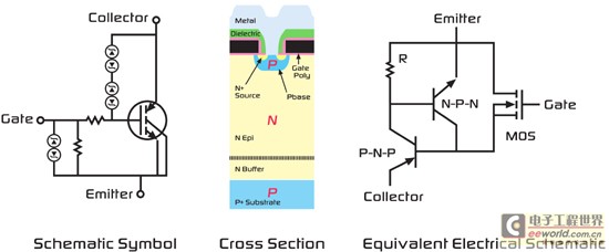
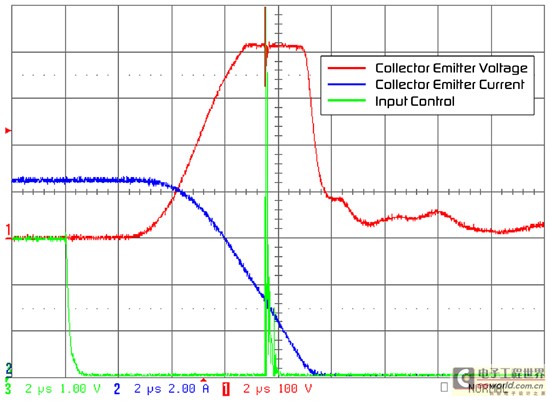

Figure 4: Current limiting circuit 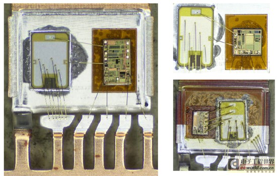
November 29, 2023