Introduction Wireless Sensor Networks is the result of a combination of communication technology, computer technology, sensor technology and network technology. The wireless sensor network is composed of a large number of randomly distributed sensor nodes with real-time perception and self-organization ability. It has the advantages of high monitoring accuracy, good fault tolerance and wide coverage area due to distributed processing. It is monitored and consumed in the environment. It has broad application prospects in many fields such as electronics, military reconnaissance and traffic management, and is one of the hotspots of international research in the near future. This article refers to the address: http:// 1 Wireless sensor network node hardware design In the process of data transmission using GPRS module, in order to facilitate system testing, this paper uses the one-way two-wire serial port DBG COM provided by AT91SAM7S256 to display the data sent by the CPU to the GPRS module, and uses the remaining USARTO to display the data sent by the GPRS module to the CPU. It realizes monitoring and parsing of sending and receiving data, and provides a good interface for debugging system functions. 2.2 ARM processor clock circuit design AT91 SAM7S series microcontroller system clock is provided by the clock generator, which includes a phase-locked loop (PLL), a main oscillator and an RC oscillator. The clock generator provides the following clocks for the system: SLCK slow clock. Provided by the RC oscillator, it is the only constant clock in the power management system. MAINCK main oscillator output clock. PLLCK divider and PLL output. The vibration signal detection in this paper is realized by ADXL202. ADXL202 is a new single-chip biaxial acceleration sensor designed and manufactured by American Analog Devices. The acceleration measurement range is ±2g; the dynamic test bandwidth is 0~5kHz, which can measure static acceleration, vibration and inclination. . In this paper, the acceleration sensor is used to monitor large vibration or movement to achieve the purpose of anti-theft. Since the vibration is microscopically a rapid change of the acceleration of the object, this paper uses this principle to monitor the vibration signal. Connect the XXL and Y-axis acceleration output pins of the ADXL202 to the timing counter of the CPU, and use the PWM signal of the TC capture chip to obtain the current acceleration. If the sudden change of the chip acceleration is continuously monitored, the vibration can be determined, and the acceleration can be determined. The degree of change corresponds to the strength of the vibration. Set the resistance value connected to the chip T2 pin 3. System software design The GPRS module is used for communication between wireless sensor networks, and it is one of the important components of the node. The data transmission through the GPRS module essentially utilizes the interconnection between the mobile communication network and the Internet network, and thus the transmitted data needs to conform to the TCP/IP protocol standard of the Internet network. The wireless sensor network node uses GPRS to realize the data transmission process: firstly, the ARM processor is used to control the MC39i module to connect with the Internet network, and the IP address is obtained through the PPP protocol; then the data encapsulated by the TCP/IP and PPP protocols is passed through the RS232 serial port. Send to MC39i. According to the communication procedure of GPRS dial-up Internet and the control description of MC39i module, this paper designs the system flow chart shown in Figure 6 to complete the GPRS module dial-up Internet access and subsequent data transmission processing, among which PPP negotiation processing and data TCP/IP and application layer Package processing is the focus and difficulty of this module design. 3.2 MC39i driver design MC39i module driver design mainly includes USART driver design under FreeRTOS, initialization of MC39i module and GPRS network parameter setting. It provides a channel for data transmission under the premise of ensuring the availability of the GPRS module, and provides a convenient interface for the implementation of the link layer and the upper layer protocol. protection board Shenzhen Zhifu New Energy Co., Ltd. , https://www.sunbeambattery.com
1. System scheme design The basic component of the wireless sensor network is the embedded node with information acquisition and communication functions. Therefore, the design of the wireless sensor network is also the design of the node. According to the functional requirements of the wireless sensor network, according to the idea of ​​embedded system body tailoring, each functional module component is selected, and the hardware structure of the embedded wireless sensor network node is designed by considering the cost performance and scalability of the node. According to the functional requirements, each independent function is modularized, and the hardware architecture of the node is shown in Figure 1. 
This article integrates the hardware platform factors, the system software uses the embedded real-time operating system FreeRTOS. Since the cluster head node needs to have GPRS data transmission function, it is also very important to have a TCP/IP protocol stack in the software system. This paper chooses the embedded real-time operating system FreeRTOS published on the famous open source website SourceForge as the basis of the system software system design, and chooses the uIP that has been ported to FreeRTOS as the system TCP/IP protocol stack. In the design of the node networking module, this paper transplants the software conforming to the ZigBee specification, which provides the basis for the development of application layer programs such as networking and routing of nodes. Figure 2 shows the software architecture of the system. 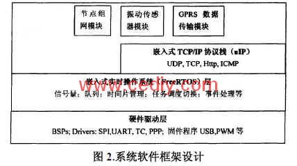
2 1ARM processor module communication circuit design 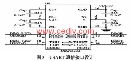
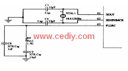
Figure 4 clock module circuit schematic
2.3 MC39i module circuit design GPRS module design can be divided into three parts: SIM card interface circuit, start reset circuit and control interface circuit. Start the reset circuit design, after the MC39i is powered on, pull the IGT pin low for at least 100ms, that is, the MC39i can be turned on; the MC39i has a SiM card interface that conforms to the ISO 7816-3 IC card standard, and the user can conveniently access the external SIM read. Cards; MC39i provides an ITU-T DCE-compliant RS232 interface through the ZIF socket, and can send AT commands and data to the MC39i via the RS232 interface. This interface operates at CMOS levels. The MC39i's RS232 interface supports 8-bit data, no parity, and 1-bit stop bit data format. The baud rate can be set from 300bps to 115kbps. Support RTS/CTS hardware handshake signal and XON/XOFF handshake signal.
2.4 vibration sensor module design
1.25MS2, so that the output signal period is l 0ms, so as to obtain better resolution, the schematic diagram is shown in Figure 5. 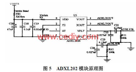
3.1 GPRS module software design 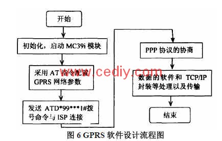
The working process of the serial port driver is: when a task needs to send data through the serial port, it must first obtain the semaphore of the serial port sending queue before sending the data, and release the semaphore after the sending ends; if the semaphore cannot be obtained, the hang The task waits for the semaphore to be valid. The driver sets up two queues for the send queue and the receive queue for the USART. When the send queue is not empty, the transmit interrupt is enabled, so that the data in the send queue is sent to the serial port through the serial port interrupt service routine. If you need to send data, just call the xSerialPutChar function to transfer data to the send queue. If you need to receive data from the serial port, you need to call the xSerialGetChar function to wait for the data to be received from the queue. The serial port driver can enable the USART to receive the interrupt and receive the data. In preparation, the serial port receive interrupt service will automatically send the received data to the serial port receive queue.
The code to set up the send and receive queues is as follows: xRxedChars=xQueueCreate( uxQueueLength, (portBASE TYPE)sizeof( *pDataPackage)); xCharsForTx=xQueueCreate(uxQueueLength+1, portBASE_TYPE)sizeof(*pDataPackage)); where xQueueCreate is provided for the FreeRTOS operating system The API interface function that creates the queue. The first parameter specifies the depth of the queue, and the second parameter specifies the width of the queue. The driver provides the following function interface for the application: signed portBASE_TYPE xSerialPutChar( xComPortHandle pxPort, signed portCHAR cOutChar, portTickType xBlockTime) void vSerialPutString( xComPortHandle pxPort, const signed portCHAR * const pcString, unsigned portSHORT usStringLength) void Uartse Printf(char *fmt, ...);void IntSendString(char *pt) signed portBASE_TYPExSerialGetChar(xComPortHandlepxPort,signed ortCHAR*pcRxedChar, portTickType xBlockTime)
3.3 Vibration Sensor Task Design This paper uses the timing counter of the AT91 SAM7S256 processor to measure the PWM signal output of the vibration sensor ADX202. The acceleration sensor is used to measure the vibration signal for monitoring large vibration or movement to achieve the function of anti-theft. Since vibration is a rapid change of the acceleration of the object, this paper uses this principle to monitor the vibration signal. Test. Finally, it is determined that when the acceleration changes twice in more than 0.03 m/s2, a vibration alarm is issued, which can sensitively monitor events such as vehicle movement and collision, and eliminate signal fluctuations caused by other conditions. The core code for the acceleration sensor processing task is as follows:
Void vADXLTask( void *pvParameters) { (void)pvParameters;
InitTC1Capture();//Initialize TC1, 2 working mode InitTC2Capture();
While(1) { xQueueReceive(ADXLCapDataQ, pcBuffer, xBlockTitne) pShkData=AnalysisADXLdataQ; //Analyze the resulting counter of the X, Y axis to capture the value AssertX=pdFALSE; //Reset the state variable AssertY=pdFALSE; xQueueSend(ShakeDataQ, pShkData, xBIockTime ): send the vibration signal to the queue vTaskDelay (WAIT * TICK_PER_SEC); / / task delay portENTER_CRITICAL (); startTC1Capture (); / / start the timer / counter 1 again to test t startTC2Capture (); / / start timing /Counter 2 again to measure the basin portEXIT_CRITICAL(); } }
4 Summary This paper is innovative: wireless sensor network is a new way of information acquisition and processing, with a wide range of application prospects. Based on the analysis of the research status at home and abroad and the functional requirements of wireless sensor networks, this paper proposes and implements the overall scheme of using ARM processor to design wireless sensor network car alarm system with embedded technology, and focuses on the hardware and software aspects of nodes. Research, using embedded ARM processor, combined with GPRS communication module MC39i, vibration sensor realizes the hardware design of a high-performance wireless sensor network node. In actual use, the system has high sensitivity, stable operation and high practical value.
November 30, 2023