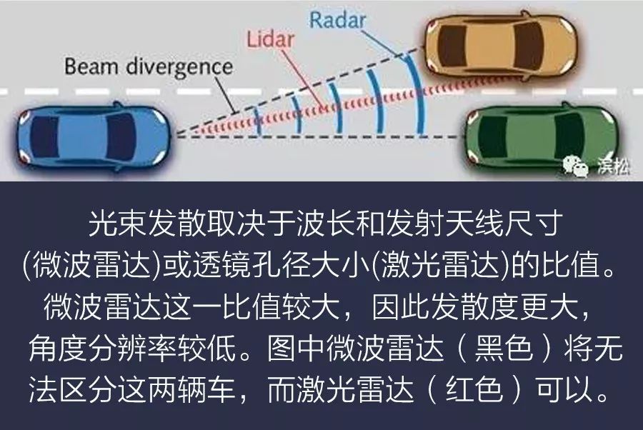
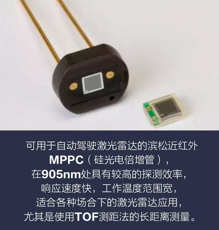
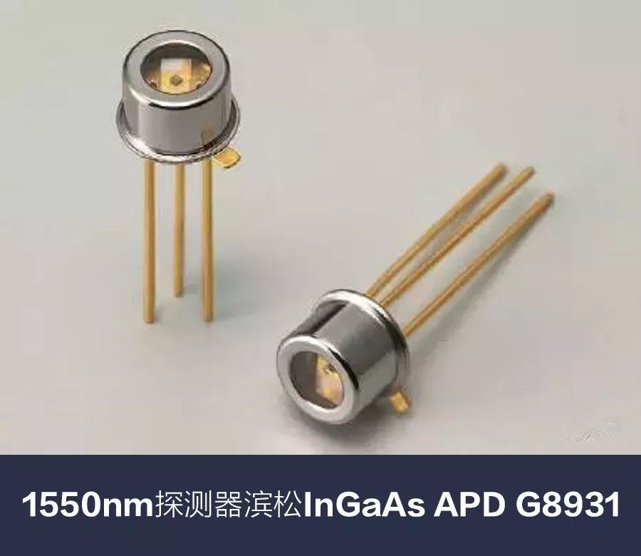
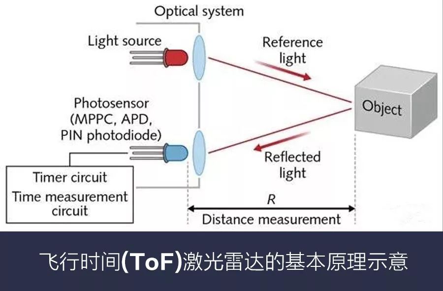
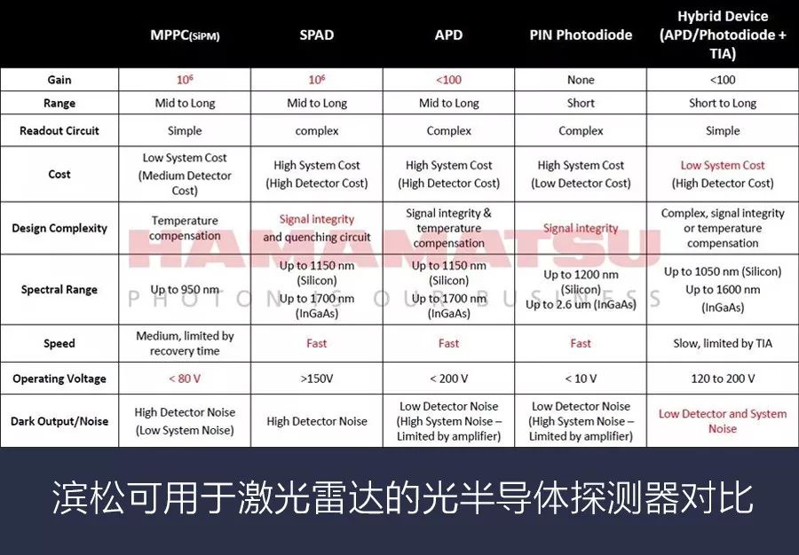
Source: Sensor Technology Lidar and its competing sensor technologies (cameras, radar, and ultrasound) have strengthened the need for sensor fusion, and have also placed higher demands on careful selection of photodetectors, light sources, and MEMS galvanometers. Advances in sensor technology, imaging, radar, light detection technology and ranging technology (laser radar), electronic technology, and artificial intelligence have enabled dozens of advanced driver assistance systems (ADAS) to be realized, including collision avoidance, blind spot monitoring, Lane departure warning and parking assistance. The synchronized operation of these systems through sensor fusion allows a completely autonomous vehicle to monitor the surroundings and warn the driver of potential road hazards, even taking driver-independent evasive action to prevent collisions. Self-driving cars must also distinguish and identify objects in front of them at high speeds. With ranging technology, these self-driving cars must quickly build a three-dimensional (3D) map of approximately 100m distance and create high-angle resolution images up to 250m. If the driver is not present, the vehicle's artificial intelligence must make the best decision. One of the basic ways to accomplish this task is to measure the round-trip flight time (ToF) of the energy pulse from the autonomous vehicle to the target and back to the vehicle. When you know the speed of the pulse through the air, you can calculate the distance to the reflection point - the pulse can be ultrasound (sonar), radio wave (radar) or light (lidar). US demonstration of laser radar application in Hamamatsu detector DEF using the APD that is using the ToF method Of these three ToF technologies, LiDAR is the best choice for providing higher-angle resolution images because it has smaller diffraction characteristics and beam divergence and can better identify adjacent objects than microwave radars. This high-angle resolution is particularly important at high speeds, providing enough time to deal with potential hazards such as head-on collisions. â–¼ Laser source selection In the ToF Lidar, the laser emits a pulse of duration Ï„, which triggers the internal clock in the timing circuit (shown below) at the moment of launch. The light pulse reflected from the target reaches the photodetector, and the conversion generates an electrical signal output to stop the clock. This way of measuring the time to and from ToF Δt can calculate the distance R to the reflection point. If the laser and photodetectors are actually in the same location, the distance is determined by the following formula: Medium c is the speed of light in vacuum, n is the refractive index of the propagating medium (about 1 for air), and there are two factors affecting the distance resolution ΔR: the uncertainty δΔt at measuring Δt and the space caused by the pulse width Error w (w = cÏ„). The first factor represents the ranging resolution ΔR = 1/2cδΔτ, while the second represents the ranging resolution ΔR = 1/2w = 1/2cÏ„. If the distance is measured with a resolution of 5 cm, the above relation means that δΔt is about 300 ps and Ï„ is about 300 ps, ​​respectively. Time-of-flight laser radar requires photodetectors and subsequent electronics to have little time jitter (a major contributor to δΔτ) and pulsed lasers that can emit short pulse widths, such as relatively expensive picosecond lasers. The current laser in a typical automotive lidar system produces a pulse of about 4ns duration, so reducing the beam divergence is necessary. The beam divergence depends on the ratio of the wavelength and the size of the transmitting antenna (microwave radar) or the lens aperture size (laser radar). Microwave radar has a large ratio, so it has a larger divergence and a lower angular resolution. The microwave radar (black) in the figure will not be able to distinguish between the two cars, but the laser radar (red) can. One of the most critical choices for automotive laser radar system designers is the wavelength of light. There are several factors that limit this choice: Human vision safety Atmospheric propagation characteristics Laser availability and availability of photodetectors The two most popular wavelengths are 905 and 1550 nm, and the major advantage of 905 nm is that silicon absorbs photons at this wavelength, while silicon-based photodetectors are generally much better than indium gallium arsenide (InGaAs) near-infrared detectors needed to detect 1550 nm light. Cheaper. However, the 1550nm human vision is much safer, and it is possible to use a laser with a single pulse of higher radiant energy—an important factor in the choice of wavelength of light. Atmospheric attenuation (under all weather conditions), scattering of particles in the air, and the reflectance of the target surface all depend on the wavelength. Due to the wide variety of possible weather conditions and reflective surfaces, the choice of wavelength for automotive laser radar under these conditions is a complex issue. In most practical cases, the light loss at 905 nm is smaller because the moisture absorption at 1550 nm is greater than at 905 nm. â–¼ Optical detector selection Only a fraction of the pulsed photons can reach the active area of ​​the photodetector. If the atmospheric attenuation does not change along the pulse path, the divergence of the laser beam is negligible, the spot size is smaller than the target, the incident angle is normal to the detector and the reflector is Lambertian (reflects in all directions), then the light receiving peak power P(R) )for: P0 is the peak power of the emitted laser pulse, Ï is the reflectivity of the target, A0 is the aperture area of ​​the receiver, η0 is the transmittance of the optical system, and γ is the atmospheric extinction coefficient. The equation shows that as the distance R increases, the received power decreases rapidly. For a reasonable choice of parameters, R = 100 m, the number of returned photons in the active area of ​​the detector is approximately a few hundred to several thousand, and the photons emitted usually exceed 1012. These echo photons are detected at the same time as the background photons, and the background photons do not have any useful information. Using a narrowband filter can reduce the background light reaching the detector, but it cannot be reduced to zero. The effect of background light reduces the detection dynamic range and increases the noise (background photon shot noise). It is worth noting that under typical conditions ground solar irradiance is less than 905 nm at 1550 nm. Report: Introduction to Core Semiconductor Devices for Autopilot Lidar â–¼ Get rid of the limitations of the ToF method Nantong Boxin Electronic Technology Co., Ltd. , https://www.ntbosen.com







March 19, 2023