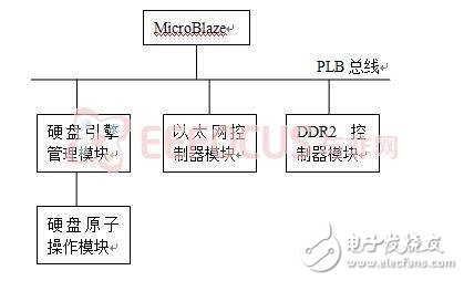
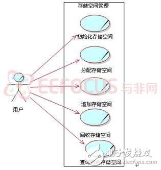
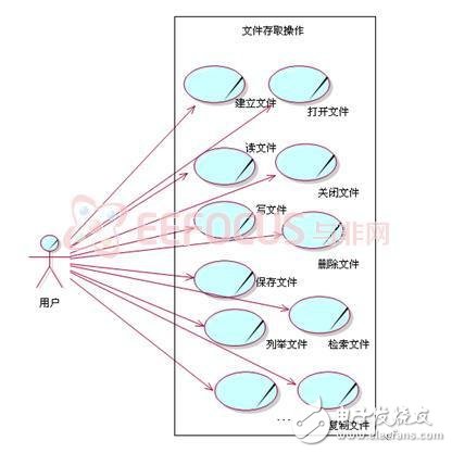
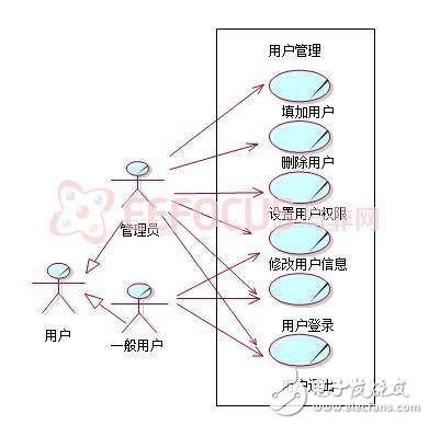
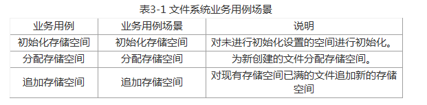
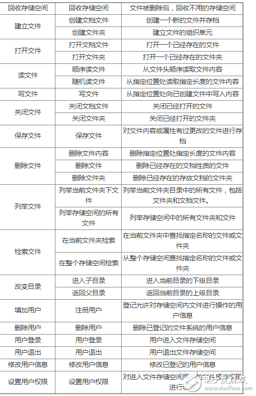
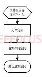
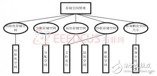
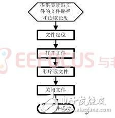
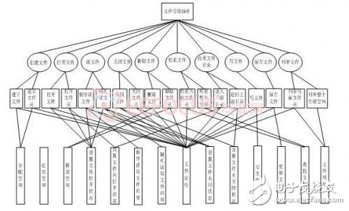
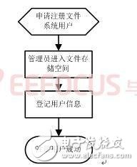
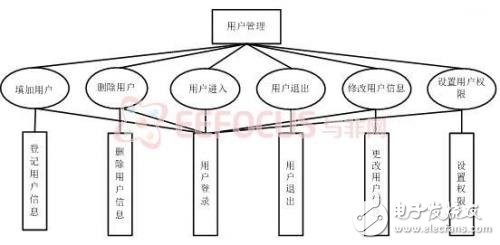
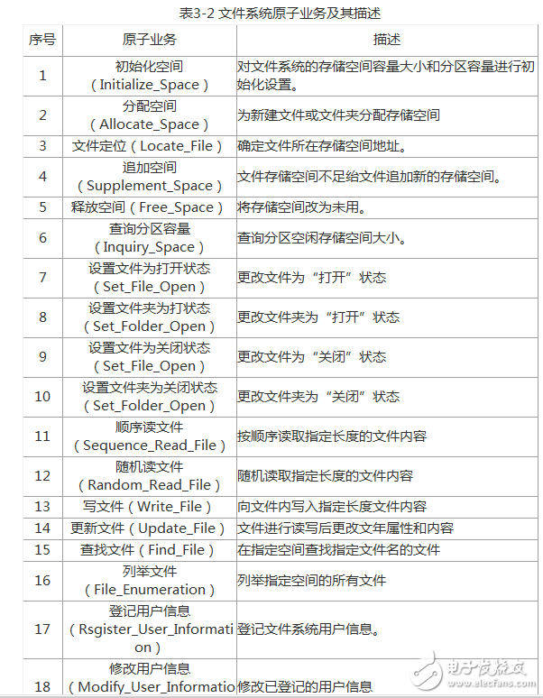
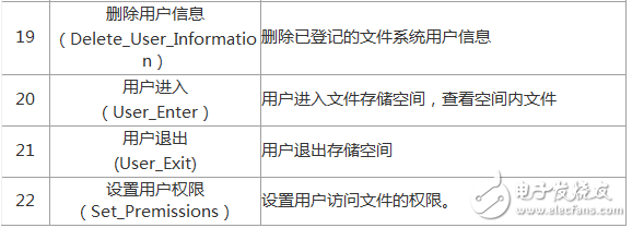
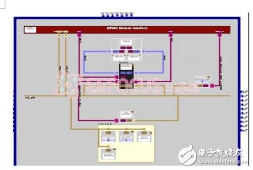
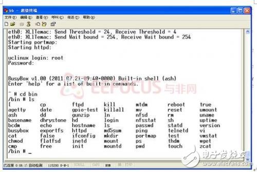
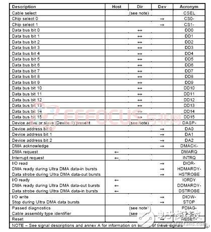
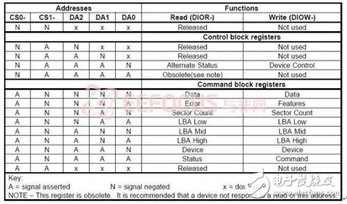
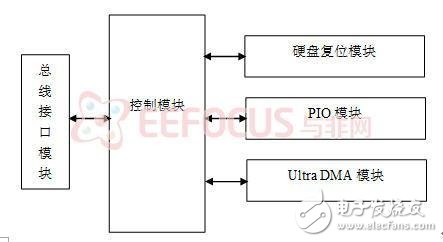
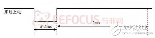
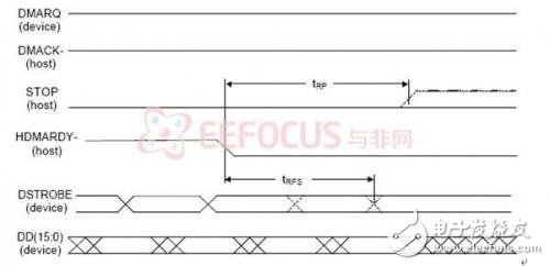
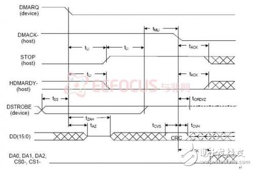
The project designed a network hard disk controller with SOA three-tier architecture using "process + engine + component". The system uses FPGA as the system controller, transplants the PetaLinux operating system on the MicroBlaze soft core processor inside the FPGA, loads the NFS network file system, encapsulates the basic hard disk operation instructions defined in the extended Int 13H specification into atomic components, and uses VHDL hardware description. The language implements each atomic component to achieve basic operations on the hard disk. The design engine module calls related atomic operations according to the NFS file system operation instructions to implement functions such as hard disk storage space management, file storage operations, and user management. In this paper, the network hard disk controller can be connected to the Ethernet as a personal storage server. Users can manage access to the server hard disk through any host connected to the network. With the popularity of e-mail and network hard disks, users can upload and download data directly through the network without carrying storage devices, and realize personal data management. However, the network hard disk provided by the network operator has limited space available and the data confidentiality is not strong. This project aims to study a network hard disk storage device suitable for personal applications. The network hard disk uses RJ45 interface to connect to Ethernet, and TCP/IP protocol through Ethernet. Users can use the host on Ethernet to manage the network hard disk. Compared with the network hard disk provided by the e-mail and network operators, the personal network storage hard disk designed by this project has the advantages of large storage capacity, safe use and high reliability. The system structure is shown in Figure 2-1. Figure 2-1 System structure The user uses the TCP/IP protocol to upload and download files through the client PC connected to the network. When uploading files, the user sends an upload file command to the network hard disk controller through the client PC, and sends the file data, and the Ethernet in the FPGA. The controller module receives the data and writes it to the DDR2 cache by the DDR2 controller module, and then reads the data from the DDR2 according to the NFS protocol and writes it to the hard disk through the hard disk controller module; when the client downloads the file, the user passes the client. The end PC sends a download file command to the hard disk controller. After receiving the command, the Ethernet controller module in the FPGA reads the file data through the hard disk controller module according to the NFS protocol and writes it into the DDR2 cache, and then the data is from the DDR2. Read and load the network protocol stack by the Ethernet controller module to send the data from the network to the client PC. The FPGA internally calls the MicroBlaze processor, transplants the PetaLinux operating system, configures the TCP/IP protocol stack, loads the NFS network file system, uses the VHDL language to design the atomic components for hard disk operations defined in the Int13H specification, and designs the engine management for atomic component calls. The module adds the atomic component and the engine management module to the PLB on-chip bus interconnected with the MicroBlaze processor in the form of a user IP core. The block diagram of the FPGA internal system module is shown in Figure 2-2. Figure 2-2 Function modules in the FPGA The SOA architecture widely used in grid computing and cloud computing technologies in the field of distributed computing in the Internet is the core design idea. Firstly, the business needs analysis is carried out, and the corresponding atomic services are found according to the analysis process of business use cases, use case scenarios and business steps. System modeling is performed according to the mapping of business atomic services to corresponding system requirements, and the sequence of scene steps is described by formal semantics as a combination of a series of atomic components. Complete the file system design of the three-tier SOA structure of "process + engine + component". 3.1 File System Business Unit A file system is a software system in the operating system that manages and stores file information. Mainly responsible for organizing and allocating file storage space, storing files and protecting and retrieving stored files. The file system mainly includes three business units: storage space management, file storage operation, and user management. Storage real-time management mainly includes the organization, distribution and recycling of storage space. The file storage operation mainly includes the basic operations of the user on the storage space file, including file generation, deletion, opening, closing, file reading, file writing, and the like. User management mainly includes user registration, login, and user rights management. 3.2 Extracting business use cases When extracting the business use cases of the file system, it mainly analyzes and extracts business use cases for each business unit of the file system from the perspective of the business protagonist-user. 3.2.1 Storage Space Management Figure 3-1 shows the use case view of the storage space management service unit. Figure 3-1 Storage space management use case view Storage Space Management This business unit mainly includes the following business use cases: initializing storage space, allocating storage space, appending storage space, reclaiming storage space, and querying remaining storage space. 3.2.2 File Access Operations Figure 3-2 shows the service use case view of the file access operation service unit. Figure 3-2 File access operation use case view The file access operation business unit includes the following business use cases: creating a file, opening a file, reading a file, writing a file, closing a file, saving a file, deleting a file, saving a file, listing a file, retrieving a file, copying a file, and the like. 3.2.3 User Management Figure 3-3 shows the user management use case view. Figure 3-3 User Management Use Case View User management The business use cases included in this business unit mainly include adding users, deleting users, user login, user exit, setting user rights, and modifying user rights. 3.3 Business use case scenario 3.3.1 Dividing Business Use Case Scenarios A business use case may have many different situations in the actual execution process. Each case is called a business use case scenario of the business use case. It can also be said that the business use case scenario refers to an instantiated use case. Table 1 shows the scenario of the business use case for the file system by analyzing the business use cases of the file system. 3.3.2 Describe the business use case In this paper, the file system business use case description uses the use case document and the UML activity diagram. By drawing the activity diagram of the file system business use case scenario, the activity diagram is described according to the format of the used document template, and the business use case model of the file system is established. , get the business requirements document of the file system. 3.4 Extracting atomic business In the previous section, the file system was modeled, and the file system's business participants, business use cases, and business scenarios were analyzed. In this summary, the atomic services of the file system were analyzed. The extraction of atomic services is mainly carried out by analyzing the main processes of the business scenario. 3.4.1 Storage Space Management Atomic Business Analysis Take the additional storage space as an example to analyze business processes. Precondition: The current storage space of the file is insufficient, and there is enough free space in the remaining storage space of the file. Postcondition: Successfully append free storage to the file. The business process consists of the following business steps: "1". Insufficient file storage space, apply for new storage space; "2". File location "3". Add new storage space. Figure 3-4 shows the business process of analyzing the above business steps and drawing the scenario of the additional storage space business use case. Figure 3-4 Additional storage space activity diagram Analysis of additional storage space This business use case can extract two atomic services: file positioning, additional storage space. After analyzing the business process of the other business use case scenarios of the storage space management service unit, the tree structure of the atomic service of the business unit is shown in Figure 3-5. Figure 3-5 Storage space management atomic business model structure 3.4.2 File Access Operations Atomic Business Analysis Analyze business processes by taking sequential read files as an example. Precondition: The file exists and is readable. Postcondition: Reads the specified length content sequentially from the specified position of the file. The business process consists of the following business steps: "1". Determine the storage space where the file is located; "2". Open the target file; "3". Read the contents of the file of the specified length; "4". Close the file. Figure 3-6 shows the service flow chart for analyzing the above business steps and drawing the scenario of the sequential read file business use case. Read the file sequentially by analysis. The business use case can extract four atomic services: file positioning, open file, sequential read file, and closed file. After analyzing the business process of the other business use case scenario of the file access operation business unit, the tree structure of the atomic service of the business unit is extracted as shown in Figure 3-7. Figure 3-6 Business activity diagram for sequentially reading files 3.4.3 User Management Atomic Business Analysis Take a registered user as an example to analyze business processes. Precondition: Have permission to become a file system user. Postcondition: The registration is successful and the user name is assigned. The business process consists of the following business steps: "1". The administrator enters the storage space; "2". Register user information. Figure 3-8 shows the service flow chart for analyzing the above business steps and drawing the scenario of the registered user service use case. After analyzing the registered user, the two atomic services can be extracted from the business use case: the user logs in and registers the user information. After analyzing the business process of the other business use case scenarios of the user management service unit, the tree structure diagram of the atomic service part of the business unit is shown in Figure 3-9. Figure 3-9 User Management Atomic Business Model Structure Through the above analysis of each business unit of the file system, the complete atomic service of the file system is extracted and its description is shown in Table 3-2. 4 Petalinux and NFS network file system transplantation The main work of Petalinux is to build the hardware platform, as well as the cutting and porting of the kernel. The hardware platform is built in the Xilinx EDK environment installed on the Windows operating system. The Virtex5-lx110t development board is selected. The Ethernet file server needs to choose the Ethernet. The IP core of the network, DDR, serial port, timer, etc. and add the corresponding interrupt, successfully build the block diagram of the project as shown in Figure 4-1. Figure 4-1 Block diagram of the construction project Then perform configuration based on Petalinux software platform, select Petalinux for operating system and library options, modify the current storage space and the current value of input and output, build the software platform, and finally generate the library and board support package, and then generate the bit stream file to download to the target. The correctness of the board test project. Petalinux is a development environment, the Linux kernel is tailored and ported. The host that installs the centos 5.6 operating system is completed. First, use the tools provided by Petalinux to create an embedded platform. Copy the project completed under Windows to the Linux system and convert to the Linux system. Format, select a new platform according to the development board, then use the make menuconfig command to enter the graphical interface of the kernel trimming, compile after reasonable cutting, and download the generated image.bin file to the DDR SDRAM of the development board through the download line, in the serial port. The terminal can see the system startup information, as shown in Figure 4-2. Figure 4-2 System startup information The network file system supports a file system protocol that accesses data located on the server disk through the network on the client side. Most network file systems are divided into two parts: the client and the file server. The client accesses the data in the form of a logical file block. The file server uses the block map to access the real disk block, and completes the management of the disk format and metadata (such as the directory), completely shields the client, the general client and the file server. Communicate by TCP/IP. NFS is the abbreviation of Network File System. It is an integral part of distributed computer system. It can share and assemble remote file system on heterogeneous networks, allowing computers of different operating systems to share data. NFS server migration: nfs server implementation requires kernel nfsd support plus two application suites portmap and nfs-uTIls, transplant this application in Petalinux, download the source code of this application, add to the usr directory of petalinux, modify the makefile And the config.in file, reconfigure the kernel to support the nfs server side, and cross-compile the application, copy the generated executable file to the bin directory of romfs, and then add the exports file in the etc directory to set the mountable The directory makes the Petalinux system have the functionality of the nfs server. IDE (Integrated Drive Electronics) is a hard disk drive developed by Compaq and manufactured by Western Digital. The IDE is based on the early ST506 hard drive. It is connected by a 40-wire single-group cable. The reliability of data transmission is enhanced, and the hard disk is easy to manufacture because manufacturers don't have to worry about their hard disk. Compatible with controllers from other manufacturers, it is more convenient for users to install them. Therefore, the IDE interface is actually a system-level interface, so it is also called an ATA (Advanced Technology Attachment) interface. (ATA is closer to the protocol layer standard of the interface, and the IDE is mostly used to describe the physical structure of the interface.) The transmission methods mainly include PIO and DMA. The ATA interface specification has evolved from the original ATA-1 version to the ATA-7 version. 5.1 Hard disk interface signal The communication connection signals between the host and the device side defined in the ATA/ATAPI-6 standard are shown in Table 5-1. The left side is a description of the signal, the middle indicates the direction of transmission of the signal (from the host to the device or from the device to the host), and the right side indicates the name of the signal. CS (1:0)-: The chip select signal sent by the host to the hard disk to realize the selection of the register; DA (2:0): The address signal sent by the host to the hard disk to address the hard disk registers; DD (15:0): The data connection line between the host and the hard disk. When the host reads and writes to the hard disk register, the lower eight bits of the data bus are used for data transmission. When the data register is read or written, the data is used. 16 bits of the bus for data transmission; DIOR-:HDMARDY-:HSTROBE: Multiplexed signal, indicating register read signal/Ultra DMA ready/Ultra DMA data output sync signal, DIOR- indicates host read signal to hard disk register, HDMARDY- indicates Ultra DMA data input, host The ready signal sent out, HSTROBE indicates the clock synchronization signal sent by the host when the Ultra DMA data is output, and the two edges are valid, that is, on the rising and falling edges of the signal, the host outputs the data; DIOW-: STOP: Multiplexed signal, indicating that the host write register command/host terminates the Ultra DMA burst transfer signal, and DIOW- indicates the host write command signal to the hard disk register. During Ultra DMA burst transfers, the host can terminate the Ultra DMA burst transfer by enabling the STOP signal. DMACK-: A response signal from the host to the DMA transfer request from the hard disk when the DMA starts transmitting; DMARQ: DMA transmission request signal sent to the host when the hard disk is ready for data transmission and reception; INTRQ: Interrupt request signal from the hard disk; IORDY: DDMARDY-:DSTROBE: I/O channel ready/Ultra DMA hard disk ready/Ultra DMA data input sync signal from the hard disk. IORDY indicates that in the PIO data transmission, when the hard disk is not ready for data transmission, enabling the signal is invalid to extend the host's access time to the hard disk. DDMARDY- indicates the flow control signal sent by the hard disk during Ultra DMA data transmission. When the data is valid, it indicates that the hard disk is ready to receive Ultra DMA transmission data. If the hard disk enables the signal to be invalid, the Ultra DMA data transmission can be suspended. DSTROBE indicates the data latch signal sent by the hard disk during Ultra DMA data transmission. The host can receive data on the rising and falling edges of the signal. RESET-: The hard disk reset signal from the host is active low. Table 5-1 Hard disk interface signals 5.2 Hard Disk Interface Register The host's access to the hard disk is achieved through access to the interface registers. Table 5-2 lists the hard disk interface registers specified by the ATA-6 standard. These registers are divided into Command Block registers and Control Block registers according to their functions. The command register is used to receive various commands and transfer data from the host, including data registers, sector count registers, and so on. The control registers are used to control hard disk operations, such as enabling hard disk interrupts, selecting hard disks, and so on. Table 5-2 Hard disk interface registers 5.3 Hard Disk Controller Module Design Figure 5-1 shows the internal structure of the hard disk controller module. Figure 5-1 Internal structure of the hard disk controller module 5.3.1 Bus Interface Module The bus interface module is a connection module of the hard disk controller and the PLB bus, and receives the operation commands and read and write data sent by the processor through the PLB bus. 5.3.2 Hard Disk Reset Module After the hard disk is powered on, it needs to complete a reset process, that is, the power-on and hardware reset protocol described in the ATA/ATAPI-6 standard. The reset process can be implemented either through software programming or by designing dedicated logic within the hard disk controller. After the system is powered on, the hard disk controller generates a low-level reset signal with a bandwidth greater than 25us through the hard disk reset module. After the reset signal returns to the high level for 2ms, the reset operation is completed. The reset signal waveform is shown in Figure 5-2. Figure 5-2 Reset signal waveform 5.3.3 PIO Module The function of this module is to generate the timing of reading and writing the internal register of the hard disk. The module generates the address line of the hard disk register to be accessed, and outputs the read/write signal. According to the data transmission direction, the data is sent to or read from the data line. After the operation is completed, release the address and data line. According to the PIO read and write timing, the module should implement the following functions: Generates an address signal that accesses the hard disk registers and has a certain effective bandwidth. The corresponding read/write signal DIOR-/DIOW- is generated. When it is a write operation, the data has a prescribed setup and hold time; when it is a read operation, the timing of reading the data is given. Handle the IORDY signal input to the hard disk. When IORDY is invalid, extend the read and write cycle of the hard disk. 5.3.4 Ultra DMA Module The Ultra DMA module is a key module of the hard disk controller. Its main function is to control the timing of Ultra DMA burst data output. The Ultra DMA operation can be divided into three phases, namely the initial phase, the data transfer phase, and the transmission abort phase. The timing of the initial phase is described as follows: When the hard disk issues the DMA request signal DMARQ, the controller responds by DMACK-, and after the DDMARDY-signal sent by the hard disk is valid, the controller starts to output the HSTROBE signal. The timing of the data transmission phase is described as follows: the rising and falling edges of the HSTROBE clock trigger the data output. During the data transmission process, the controller can suspend the data output by stopping the HSTROBE signal. The hard disk can invalidate the DDMARDY-signal. Suspend the receipt of data. In the transmission termination phase, both the controller and the hard disk can terminate the data transmission. Terminating the data transmission can be divided into four processes: stopping the request, stopping the check, HSTROBE returning to the high level, and transmitting the CRC check value. For the controller to stop data transmission, first stop generating the HSTROBE clock signal, issue a STOP command signal, the controller checks that the DDMARDY and DMARQ of the hard disk are invalid, so that HSTROBE returns to high level, makes DMACK- invalid, and DMACK-signal transition The CRC check value is output along the data line DD (15:0), as shown in Figure 5-3. For the hard disk to stop data transmission, stop the data transmission by invalidating both DDMARDY and DMARQ. The controller needs to issue a STOP signal within tL1 time, return HSTROBE to high level, invalidate DMACK-, and output CRC check value to DD ( 15:0), as shown in Figure 5-4. Figure 5-3 Controller terminates Ultra DMA data transfer timing Figure 5-4 Hard disk termination Ultra DMA data transfer timing 5.3.5 Controller Module The control module is the core of the hard disk controller. The main function of the module is to realize the CPU configuration of the registers in the hard disk controller, and implement corresponding control operations according to the written information of the relevant registers. The project designed a network hard disk controller based on the "process + engine + component" SOA three-tier architecture. Using FPGA as the system controller, transplanting the PetaLinux operating system on the MicroBlaze soft core processor, loading the NFS network file system, encapsulating the basic hard disk operation instructions defined in the extended Int 13H specification into atomic components, and implementing the atoms in the VHDL hardware description language. Component operation. The design engine management module calls related atomic operations according to the NFS file system operation instructions to implement functions such as hard disk storage space management, file storage operations, and user management. Boiler Pressure Gauge,Inflatable Pump Pressure Gauge,Mini-Sized Theromanometer Pressure Gauge,Gauge Pressure ZHOUSHAN JIAERLING METER CO.,LTD , https://www.zsjrlmeter.com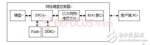
March 30, 2023