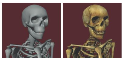
To get more realistic details, one or more texture maps will be applied to the surface of the object, as shown in the figure below. The texels of each point on the surface of the object can be found in the texture map. They follow the lighting formula in some way combined with the lighting. In the simplest case, a sample from the diffuse texture map can be used to adjust the color of the diffuse reflection.
Let the color T represent the filter sample in the texture map corresponding to one point on the surface. Using this color to adjust the diffuse color will produce an extended version of the diffuse illumination equation:
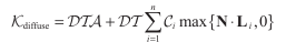
Note: The diffuse reflectance equation is: 
Just as texture mapping can be used to adjust the diffuse portion of the lighting equation, we can also use texture mapping to adjust the specular reflection. Such a texture is sometimes referred to as a gloss map, which determines the degree of specular gloss at each point on the surface. Using color to represent a filtered sample in the specular map, we can extend the specular reflection equation like this:

Note: The specular reflection illumination equation is: 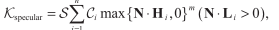
The true color of the sample obtained from the texture map is determined by its corresponding object texture coordinates. Texture coordinates are either pre-calculated, stored in each vertex of the triangle mesh, or calculated at run time to produce some special effects. Texture coordinates use formulas when rendering triangle patches
To interpolate the texture coordinates. For each vertex of the texture map, there may be 1 to 4 coordinates, which are labeled s, t, p, and q. The next few chapters will introduce several different texture maps, and in each texture map, how we use texture coordinates to find corresponding points in texture maps.
Standard texture mapping
In one, two, or three-dimensional texture maps, we use the corresponding texture coordinates to find texels. As shown in the figure below, the entire width, height and depth of the texture map correspond to the coordinates between s, t and 0 to 1 in the p direction.
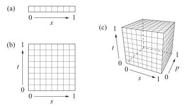
A one-dimensional texture map can be viewed as a two-dimensional texture map with only a single height-direction pixel. Similarly, a two-dimensional texture map can be viewed as a three-dimensional texture map with only a single depth-direction pixel. If the t and p coordinates are not marked, we consider them to be zero.
Projection texture map
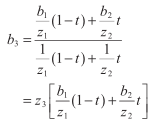
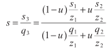
The fourth texture coordinate will be used in the projection texture map, and its application will be introduced in this section. The q coordinate value is very similar to w in homogeneous coordinates, and its value is generally 1 unless otherwise specified. The values ​​of the coordinates s, t, p will be divided by the coordinates of q. For a scan line with two endpoint texture coordinates (s1, t1, p1, q1) and (s2, t2, p2, q2), we can use the equation

To calculate the interpolated values ​​s3 and q3, the quotient of these two values ​​with the intermediate parameter gives the s-coordinate in the texture map sample:
A similar expression calculates the texture coordinates of the projected t,p.
Some projection coordinate mappings are simulations of point-light projections of surrounding environment images. As shown in the figure below, the projection of the image increases with increasing distance from the point light source. This effect is obtained by mapping the vertex position coordinates of the object to the texture coordinates (s, t, 0, q) using a 4x4 matrix, which is then divided by q to produce a 2D texture map of the correct projected image. Coordinates (s, t).
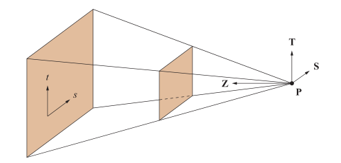
Assume that the point source direction at P is Z. Let the unit vectors S and T lie on a plane perpendicular to the vector Z so that they coincide with the s, t coordinates of the projected texture image. Each vertex position (x, y, z, 1) on a surface illuminated by a point light source must first be converted to a coordinate system whose origin is the point light source, where the x, y, and z coordinates correspond to the S, T, and Z vectors. The direction. This can be achieved using the inverse of the matrix listed as vectors S, T, Z, and P. If the vectors S and T are perpendicular to each other (ie, the projected image is not skewed), the transformation can be written as:

Note that this matrix is ​​converted to the left-handed coordinate system,
Because SXT = - Z
Now we need to use the second matrix to multiply this matrix to complete the projection. Just as we define the focal length of the perspective frustum, we define the focal length of the point source projection in the form of the tip angle a:

Let a be the aspect ratio of the texture map, which is equivalent to its height divided by its width. Each vertex position needs to be projected onto a plane that is at a distance e from the point source. Here we want to map the point in the [-1, 1] interval in the x direction to [0, 1] and to The point in the direction of [-a,a] is mapped to [0,1]. This matrix
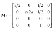
This mapping is done and the projection process is completed after the s,t coordinates are divided by q. Combining the two matrices (M1M2) given earlier, we can use the matrix M = M2M1 to derive the projected point source image.
Cube texture mapping
Another way to map the texture of an object is through the use of cube texture mapping. Cube texture mapping is often used to approximate the reflection of ambient light at the model surface. As shown below, the cube texture map contains six two-dimensional components that correspond to the six faces of the cube. The s, t, and p coordinates express the direction vector from the center of the cube that points to the sample pixel.
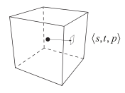
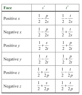
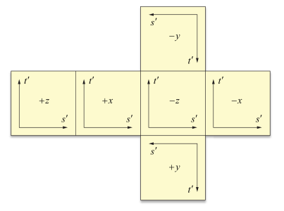
Which face the sample corresponds to depends on the sign of the coordinate with the largest absolute value. The other two coordinates are divided by the largest coordinate value and then remapped to the range [0,1] using the table below to generate the 2D texture coordinates (s',t'). This coordinate will be used to sample the 2D texture map for the corresponding cube texture map. The following figure shows the cube map coordinates and the orientation of the corresponding 6 faces.
The combination of texture coordinates and cubic texture mapping is usually generated at runtime. For example, the environment map can be implemented by calculating the reflection of the camera direction and storing it in the (s, t, p) coordinates of each point of the triangle mesh. The calculation of the reflection direction is generally done in hardware, so this can be done very efficiently.
The application of cube texture mapping in some graphics hardware is a normalized vector. A standardized cube map is a vector group that stores color-coded RGB colors on six sides, rather than a cubic texture map that stores color images. The vector array it stores is in the following form:
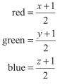
In the cube map, the vector stored in each surface pixel is the unit length vector (s, t, p) of the pixel sample. The use of standardized cube maps is very appropriate when performing some per-pixel lighting, because normal interpolation on triangle surfaces can produce some normal vectors less than 1 in length.
Cable Management,cable organizer,wire management,cable cover wall
NINGBO UONICORE ELECTRONICS CO., LTD , https://www.uonicore.com