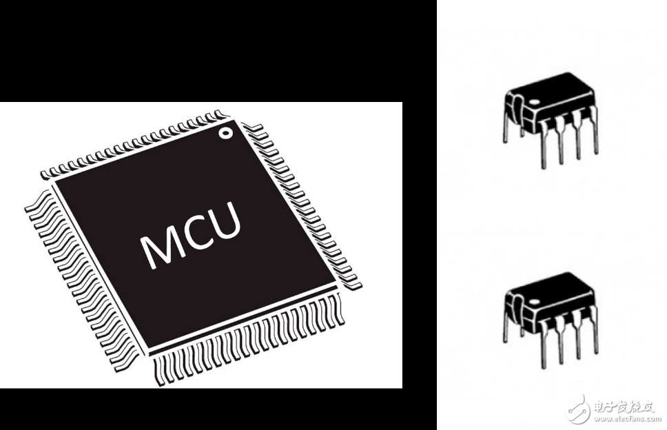
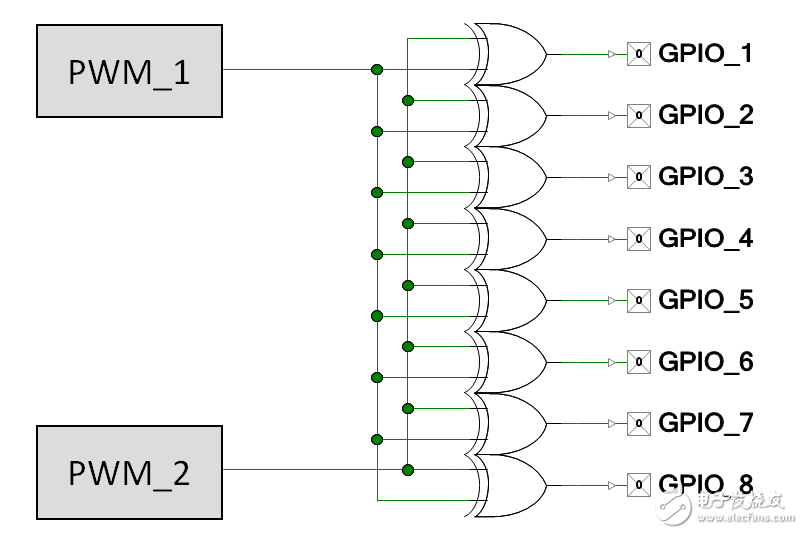
In system integration and board design, engineers often need to implement pin level digital logic based on input and output signals. The use of external independent logic components typically results in increased material costs and is therefore not suitable for low cost systems. In addition, the microcontroller needs to have efficient power to achieve long-term operation of the battery-driven device. These problems can be solved at the chip design level by adding programmable logic blocks to the input and output ports to integrate board-level glue logic functions associated with input and output, and to reduce some of the microcontroller's signal processing tasks and reduce equipment. Power consumption. We provide application examples such as LED control to demonstrate the role of logic gates in reducing material costs and device power consumption. Chip design engineers often need to implement pin level digital logic based on input and output (I/O). For example, when a system engineer uses a microcontroller to clock multiply, it is often necessary to create a clock tree, input the input clock to multiple buffer clocks (with appropriate drive capability), and/or reverse the clock polarity. In many scenarios, system engineers must logically combine I/O signals. Their usual solution is to use the external components such as discrete combinatorial logic modules to implement the last-minute changes, using "blue wire" to connect the components. This not only increases the cost of materials, but also affects the time-consuming rotation steps in the production of PCBs. Figure 1 MCU + Discrete Logic Chip With the rapid growth of battery-powered devices, power consumption has become an important concern for system engineers. Each time you save a little power, you will extend the battery's charge time. As a result, system engineers attempted to perform some simple I/O signal processing tasks on the hardware to reduce CPU load—the CPU is the main power consuming component of the system. For example, by inputting two pulse width modulation (PWM) signals to the XOR gate, the output signal can be used to implement the breathing lamp. The two PWM signals have a small frequency difference, and the beat frequency generated by the frequency difference is the desired breathing frequency of the breathing lamp. In this scenario, if the running logic is implemented in the firmware, the CPU will not need to start at a fixed time. Figure 2 Hardware implementation of 8 breathing lights Stand Table Fan ,14 Inch Oscillating Table Fan,Pedestal Table Fan,Height Adjustable Table Fan Foshan Shunde Josintech Electrical Appliance Technology Co.,Ltd , https://www.josintech.com

March 17, 2023