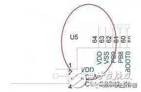
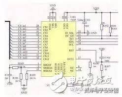
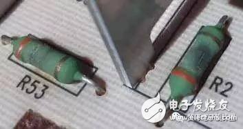
1. Is there a polarity capacitor, the schematic and the PCB are reversed? 2. The power supply and the ground have forgotten to pick up. . . . There is also a reversal. . . 3, the Connector 's line order is reversed 4. RX and TX are reversed. . . When the serial port RX, TX is drawn, don't reverse it, don't reverse it, the board patch will come back to test, and the serial port will not work. 5, of course, write a package, the result is no device of this specification. Baidu library download datasheet, the results can not buy this device. 6, directly copy the circuit, the results of the device can not buy. Once a team that made smart locks, the circuit directly copied Samsung's smart lock. As a result, a capacitive touch button controller was hard to buy in Korea, and there was no agent or support. Test and explore on your own. 7. When selecting a capacitor, only consider the capacity, and do not consider the withstand voltage. As a result, such a large package cannot fit the specification capacitor. 8, when choosing a resistor, only look at the resistance value, do not look at power consumption. 9, after finishing the PCB, do not look at the DRC report, relying on the eyes to see the flying line, after returning to the board, it is really flying. When the brain was disabled, the short circuit DRC was turned off, and as a result, the board power supply was positive and negative. 10, the package is reversed. . . At that time, I was in a hurry. I didn’t get the chip. I only looked at the Datasheet and drew the picture and cast the board. When the board came back, I looked at the mirrored package and looked at it. But this can't blame me, because the package diagram on the silly x datasheet is actually a bottom view and it is not specified! 11. The solder mask of the thermal pad is not processed. 12, lm1117 the whole picture is reversed, ina826 the opposite end of the opposite end of the wrong side of the schematic is drawn wrong. . When I burned the program, I forgot to choose the external crystal oscillator and then measured it for a long time and found that I rubbed and burned the program. 13, 431 is a wonderful design, check the order of the pins several times each time Regarding the pin arrangement of the 431 regulator SOT23 package, it turns out that the order of each manufacturer is the same. As a result, it was found that from left to right, TI-TL431A is a CAR array, and UTC-TL431A and CJ431A are RAC arrays. There is also a relay pin arrangement. The document is usually given a bottom view. As a result, there is no mirror image when the board is drawn, so the relay is soldered to the back. 14, against the datasheet to reverse the package, vowed to say that this is the most beautiful piece of my layout 15, as long as the board has a daughter card, then wait for the palm of your hand inexplicably sweating, sleep is scared to wake up. 16, the battery interface polarity is reversed. . lost heavily Common eight misunderstandings with circuit design Phenomenon 1: The PCB design requirements of this board are not high, just use a thin line and automatically cloth it. Comments: Automated wiring must occupy a larger PCB area, and at the same time produce more than a lot of vias than manual wiring. In large batches of products, the factors considered by PCB manufacturers to cut prices are line width and The number of holes, which affect the yield of the PCB and the consumption of the drill bit, respectively, saves the cost of the supplier, and finds a reason for the price reduction. Phenomenon 2: These bus signals are pulled with a resistor, and I feel relieved. Comments: There are many reasons why the signal needs to be pulled up, but not all of them have to be pulled. The pull-down resistor pulls a simple input signal, and the current is tens of microamps or less. However, if a signal is driven, the current will reach milliamperes. The current system is usually 32 bits of address data, and there may be After the 244/245 isolated bus and other signals are pulled up, a few watts of power is consumed by these resistors. Phenomenon 3: How to deal with these unused I/O ports of CPU and FPGA? Let it be empty first, and then talk about it later. Comments: If the unused I/O port is left floating, it may become an input signal of repeated oscillations due to a little interference from the outside world, and the power consumption of the MOS device basically depends on the number of times the gate circuit is flipped. If you pull it up, each pin will also have a micro-ampere current, so the best way is to set it as an output (of course, you can't connect other driven signals outside) Phenomenon 4: There are so many doors left in this FPGA, so let's play it out. Comments: The power consumption of FGPA is proportional to the number of flip-flops used and the number of flips, so the power consumption of the same model FPGA at different times of different circuits may differ by a factor of 100. Minimizing the number of flip-flops at high speeds is the fundamental way to reduce FPGA power consumption. Phenomenon 5: The power consumption of these small chips is very low, no need to consider Comments: It is difficult to determine the power consumption of the chip that is not too complicated inside. It is mainly determined by the current on the pin. An ABT16244 consumes less than 1 mA without load, but its indicator is each foot. Can drive 60 mA load (such as matching tens of ohms of resistance), that is, the maximum power consumption of up to 60 * 16 = 960mA, of course, only the power supply current is so large, the heat is falling on the load. Phenomenon 6: The memory has so many control signals. I only need to use OE and WE signals on this board. The chip selection is grounded, so the data is much faster when reading. Comments: Most of the memory power consumption is more than 100 times larger than when the chip select is valid (regardless of OE and WE), so CS should be used to control the chip as much as possible, and if other requirements are met, It is possible to shorten the width of the chip select pulse. Phenomenon 7: How do these signals have overshoot? As long as the match is good, it can be eliminated. Comments: Except for a few specific signals (such as 100BASE-T, CML), there are overshoots. As long as they are not very large, they do not necessarily need to match, even if the match is not the best match. The output impedance of TTL is less than 50 ohms, and some even 20 ohms. If such a large matching resistor is used, the current is very large, the power consumption is unacceptable, and the signal amplitude will be too small to be used. In addition, the output impedance of the general signal at the output high level and the output low level is not the same, and there is no way to achieve a perfect match. Therefore, the matching of signals such as TTL, LVDS, and 422 can be accepted as long as the overshoot is acceptable. Phenomenon 8: Reducing power consumption is a matter for hardware personnel, and it has nothing to do with software. Comments: The hardware is just a stage. The software is the software. The access of almost every chip on the bus and the flipping of each signal are almost controlled by software. If the software can reduce the number of external accesses (use more register variables, More use of internal CACHE, etc., timely response to interrupts (interrupts are often active low with pull-up resistors) and other specific measures for specific boards will greatly contribute to reducing power consumption.
Special requirements for medical power wire harness:
Reliable power supply is the basis to ensure the long-term use of medical equipment. Kable-X provides power Cable Assembly and power extension cord assemblies for many internationally renowned companies. The wiring harnesses are widely used in ventilators, defibrillators, surgical equipment, health equipment and other medical devices that are related to life safety. Therefore, we pay special attention to the quality of our products. Kable-X is a manufacturer certified by UL and ISO. Our production is also strictly in accordance with the IPC/WHMA-A-620 standard.
We produce a large number of Medical Cable Assembly, including Medical Power Wire Harness, Medical Defibrillator Wire Harness and Medical Aid Equipment Wire Harness.
Medical Power Wire Harness,Cable Assembly Flat,Custom Flat Cable,Electrical Harness Assembly Kable-X Technology (Suzhou) Co., Ltd , https://www.kable-x-tech.com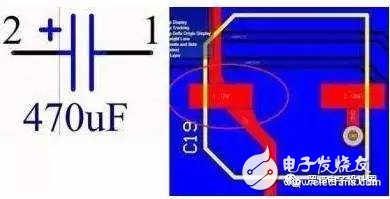


At present, most medical equipment adopts switching power supply. With the development of electronic technology, switching power supply is not only greatly reduced in size and weight, but also greatly reduced in energy consumption and improved reliability. Medical diagnostic, measurement and treatment equipment using AC power equipment, may cause leakage currents due to improper grounding and electrical insulation, exposing patients and medical personnel to potential hazards such as electric shock, burns, damage to internal organs, and arrhythmias.
In view of the special use environment of medical equipment, medical power Wire Harness has more stringent requirements in terms of safety and reliability.
Welcome to contact our sales and engineers to discuss your products together!

December 24, 2022