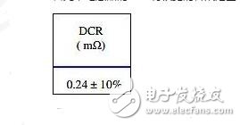
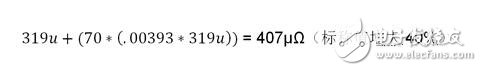
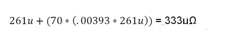
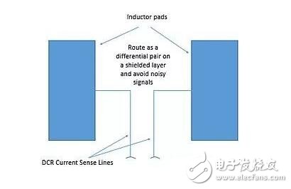
One of the challenges of a power system design is current sensing. One popular "no-overhead" approach in buck converters is DCR current sensing. However, this circuit is very inaccurate, especially when using small, low-ESR inductors, so it will be replaced by other methods, such as current sense resistors, or power link devices. Buck converters are the most common power topology, and power engineers know their strengths and weaknesses. One of the challenges in power system design is current sensing. One popular "no-overhead" approach in buck converters is DCR current sensing. It is said to be "no overhead" because it does not add extra cost or power to the power supply design, but it is well known that this circuit is very inaccurate, especially when using small, low ESR inductors. This is even more so. Let's take a look at the composition of the DCR detection circuit. This circuit is simple enough: add an RC network to the output inductor and generate a differential signal. The RC network converts the inductor current into a voltage across C1. Figure 1: DCR current detection circuit. The calculation of the RC value is simple enough, RC = L / DCR, where: L = inductance value of L1; DCR = DC resistance of inductor L1; R = R2 in the schematic of Figure 1 (or, if R3 is present, is the parallel connection of R2 and R3); C = C1 in the schematic of Figure 1. Please note In Figure 1, if the amplitude of the ISENSE peak signal saturates the differential amplifier, then R3 is increased to reduce the peak signal amplitude to within the specified range of the differential amplifier. “No overhead†is always popular, but it is often said that “cheap is not good, good goods are not cheapâ€. The accuracy of this circuit is very poor. First, the DCR of the inductor has a wide tolerance range, ± 7% or even ± 10% is very common. Figure 2: Typical specifications for an inductor DCR. If the initial tolerance is 10%, the DCR of the 180nH inductor shown in Figure 1 may be as low as 261mΩ or as high as 319mΩ. To make matters worse, the inductor will heat up, and the temperature coefficient of the copper wire winding is 3930 PPM/oC or 0.393%/oC. If the applied temperature rises to 35oC above ambient temperature and the inductor itself heats up and raises the temperature by another 35oC, then the nominal DCR may rise to: The worst case limit is: The lower limit of the worst case is: (The nominal value is increased by 15%. The total error will be lower because the positive coefficient of the copper wire compensates for the low initial value of the inductor.) From an engineering point of view, this is really bad because overcurrent markers and overcurrent shutdowns are based on these resistors. If the circuit is too sensitive, it will stop if it does not reach the level of downtime. This is not the result we want. If the circuit is not sensitive, there is a risk of excessive pressure on the inductor and power FET. This is not the result we want. How bad can the situation be? Assume that a circuit that provides a maximum of 35A at 1V is being designed (this value is reasonable for a practical single-phase buck converter). If the inductor DCR is at the low end of the tolerance, then the controller assumes that 40A is provided when the output is 35A. This means that the OCP cannot be set to less than 40A, otherwise the power supply will stop at the nominal load. Conversely, when the OCP is set to 40A and the inductor DCR is increased by 10%, how bad is the situation? In this case, the actual load current is 40A, but the DCR is 407μΩ, so the controller considers the output current to be 65A. This means that the OCP needs to be set to 65A. If it is not set to this value, there is a risk of OCP shutdown when it is less than 40A. This seems unacceptable, but once the OCP is set to 65A, the circuit must be designed to provide such a large current continuously, even when the current is accurately reported. This means that the output inductor and power FET are heavily over-engineered, and the power supply must provide 35A, but it must be designed to provide 65A continuously. Moreover, to make matters worse, the current in the inductor has peak-to-peak ripple in addition to the DC component. How big is this ripple? For ripple currents, the usual design principle is 20%. This means that the cycle-by-cycle current limit must be set higher than 65A, so the ability to protect the output FET becomes very problematic. Guess what happens if you design for 30% ripple current? Then, you will realize that the typical current sense voltage range is 10mV to 20mV. If there is a switching node ringing in one power supply, a stray magnetic field generated by the output inductor, and current flowing in the bypass capacitor and the output capacitor, it is difficult to obtain an acceptable signal-to-noise ratio (SNR). To have any hope for signal quality, the current sense connection must be carefully placed into a differential pair (hence, any noise picked up is common mode) and placed away from inductors, switch nodes, and high current/high frequencies. Current loop. This is difficult in space-constrained designs, as everything in today's space-constrained designs looks hard. Figure 3: Kelvin inductor current sense wiring. what can we do? First, the temperature of the inductor can be estimated empirically by using a thermistor or a temperature sensing diode (usually a forward biased PNP base-shot in a small transistor). In this way, the thermal response of the copper wire winding resistance can be adjusted. This is too helpful. The engineers are really amazing. If we do it very carefully, then the best result is likely to reach ±10%. What else can we do? We can ignore the "no overhead" DCR circuit and connect an expensive, temperature-stable current sense resistor in series with the output inductor. This adds cost and compromises the efficiency of the converter, but with good differential signal routing, we are able to detect the output current with much higher accuracy. As the tolerance builds up, we can get an overall current sensing performance of ±5% or better. Engineers have proved the rationality of this scheme in the design review, and they have avoided the criticism of the efficiency and cost of their design. Their courage makes me admire. How about using an inductor made of temperature-stabilized alloy windings? When this idea came out, my heart was scared and mad. Is there any other way? There is something better than a current sense resistor. Let the power link device report its current. This approach uses a well-designed Smart Power State (SPS) that, while increasing the cost of current sensing, provides peak power capability that is very close to the nominal output requirement. The result is a significant reduction in waste caused by over-engineering the power link components. How much expectation can we put on this current detection method? For a reasonable operating area (do not expect a miracle when the output current is near zero), we can get an initial accuracy of ±1%, with a worst tolerance of ±2% with aging and temperature changes. Year after year, advances in technology have provided engineers with increasingly better basic components. Let the "no overhead" DCR current detection circuit go with the wind. Female Header Connector,Female Header Single Row Connector,Female Header Single Row Angle Connector,Female Header Dual Row Smt Connector Shenzhen Hongyian Electronics Co., Ltd. , https://www.hongyiancon.com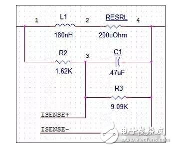

March 02, 2023